Side plate with reduced warp for heat exchanger and heat exchanger using the same

a technology of side plate and heat exchanger, which is applied in the direction of indirect heat exchanger, lighting and heating apparatus, stationary conduit assembly, etc., can solve the problems of unbalanced material stress state, side plate brought into unbalanced stress state, and it is difficult to assemble the end of the side plate in the lengthwise direction, and achieves the effect of simple pressing form

Inactive Publication Date: 2006-01-05
DENSO CORP
View PDF6 Cites 5 Cited by
  • Summary
  • Abstract
  • Description
  • Claims
  • Application Information

AI Technical Summary

Benefits of technology

[0012] The above-mentioned points being taken into account, the object of the present invention is to reduce a warp of a

Problems solved by technology

This is because a residual stress state of the material is unbalanced.
As a result, the side plate is brought into an unbalanced stress state, under stress, because of the coexistence of the contraction and stretch.
If such a large warp a occurs, it becomes difficult to assemble the ends of the side plate in the lengthwise direction to the ends of the header tanks in the core assembling process before integrally brazing a condenser.
Further when integrally brazing a condenser, a g

Method used


Image

  • Side plate with reduced warp for heat exchanger and heat exchanger using the same
  • Side plate with reduced warp for heat exchanger and heat exchanger using the same
  • Side plate with reduced warp for heat exchanger and heat exchanger using the same

Examples


first embodiment

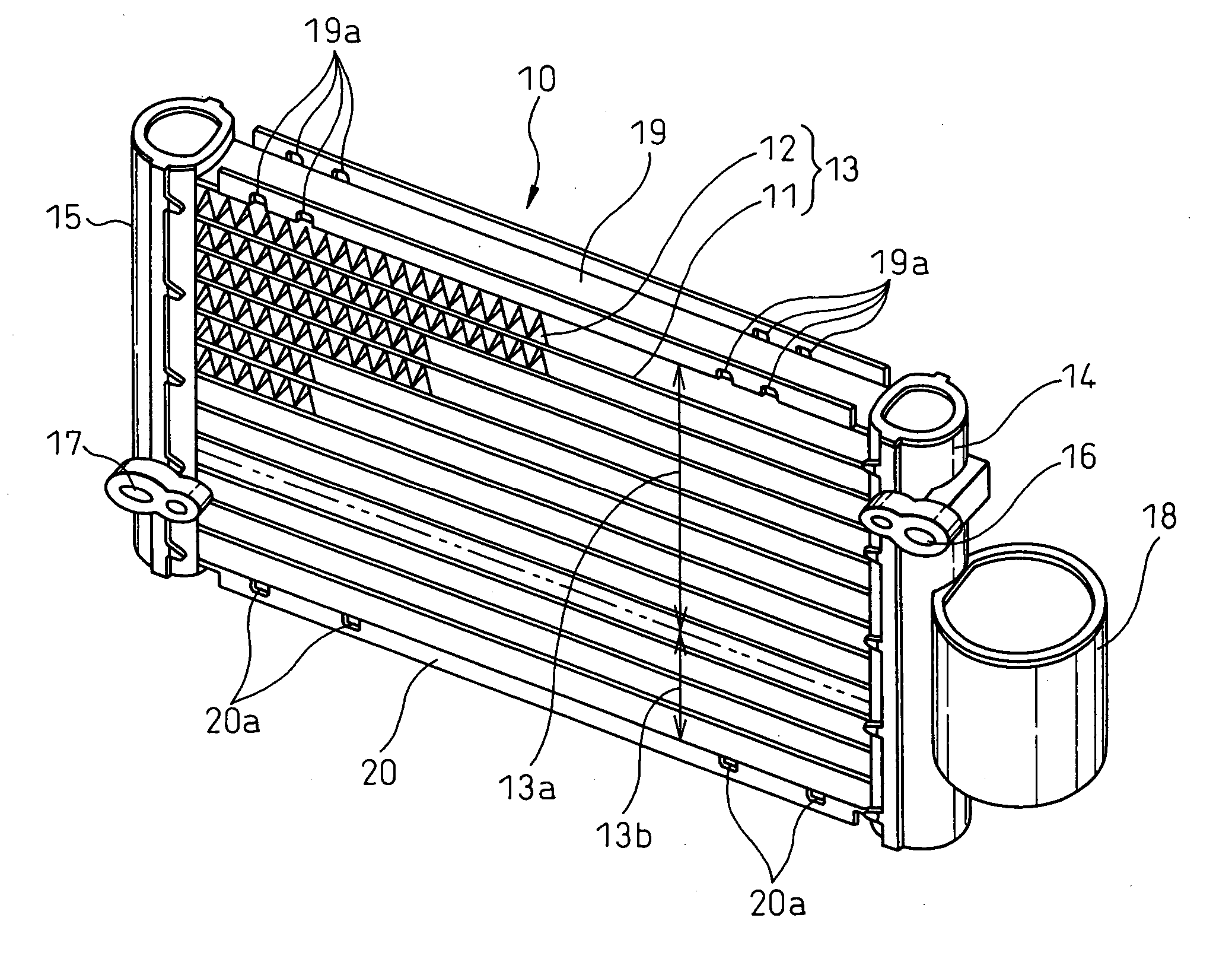
[0037] The present embodiment relates to a condenser for vehicle air conditioning and, first of all, an outline of the condenser for vehicle air conditioning is explained by referring to FIG. 1. As is widely known, a condenser 10 is connected to the discharge side of a refrigerant of a compressor in a refrigerating cycle and cools and condenses the gas refrigerant discharged from the compressor with the outside air.

[0038] The condenser 10 has a core section 13 comprising a plurality of flat tubes 11 extending in the horizontal direction and a plurality of corrugated fins 12, and on both the right end and the left end of the core section 13, header tanks 14 and 15 having a substantially cylindrical shape and extending in the vertical direction are arranged, and both ends of the flat tubes 11 are communicated with the inside of the header tanks 14 and 15.

[0039] At the upper part of the header tank 14 on one side, an inlet join 16 through which a discharged gas refrigerant, from a co...

second embodiment

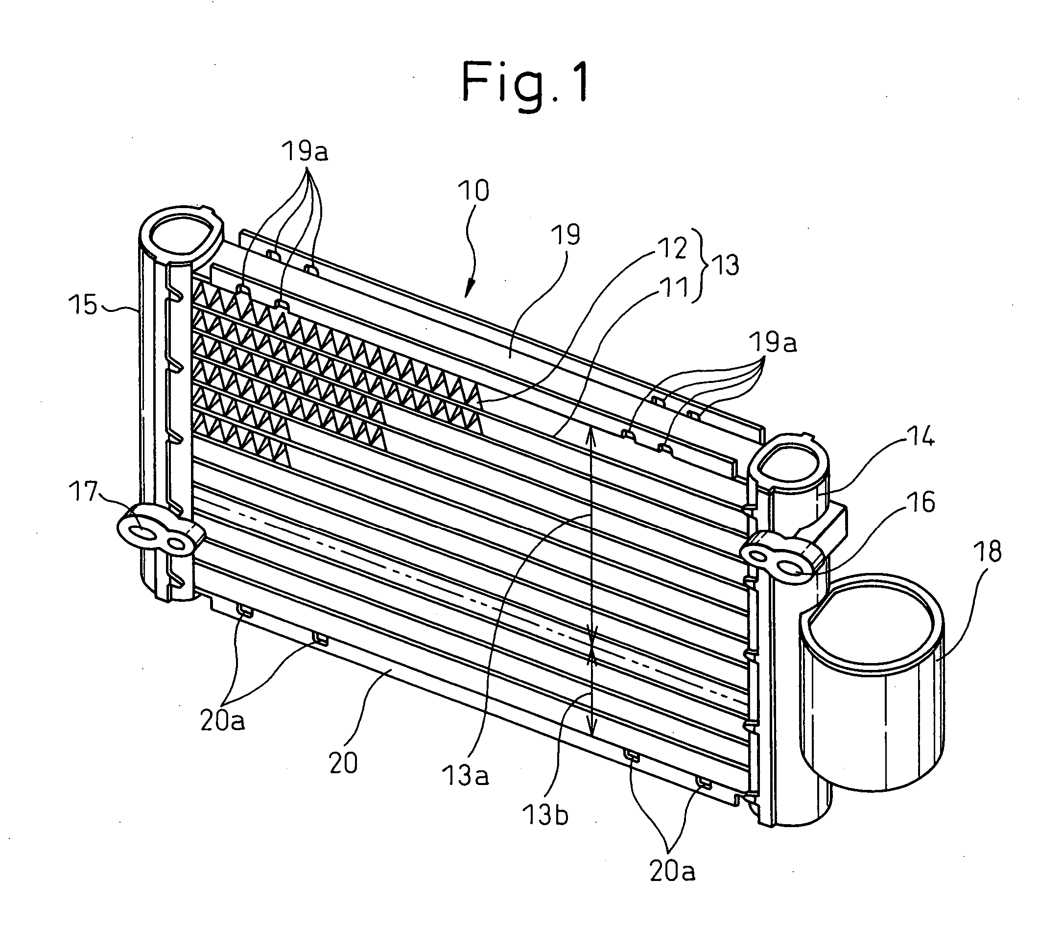
[0063] Although the recesses 24 are formed on the inner surface of the bottom section 21 of the side plates 19 and 20 having a U shaped section in the first embodiment, the recesses 24 are formed on the outer surface of the bottom section 21 in the second embodiment as shown in FIG. 4.

[0064] It has been confirmed that even if the recesses 24 are formed on the outer surface of the bottom section 21 as described above, the warp a can be reduced as in the first embodiment.

[0065] However, as is seen from FIG. 1, the corrugated fin 12 is joined by brazing to the outer surface of the bottom section 21 of the side plates 19 and 20 and, therefore, the formation of the recesses 24 on the outer surface deteriorates the joinability (brazing properties) between the side plates 19 and 20 and the corrugated fin 12. Therefore, from the viewpoint of the joinability, the first embodiment is preferable to the second embodiment.

Other Embodiments

[0066] In the above mentioned embodiments, although t...


PUM


Abstract

A warp of a side plate in the lengthwise direction is reduced by means of a simple shape formed by pressing without increasing a press machine in size. A side plate, for a heat exchanger, to be arranged at the end of a core section 13 composed of tubes 11 and fins 12 has a long and narrow shape with a U-shaped section formed by a bottom section 21 and bent sections 22 and 23 formed by bending both ends of the bottom section 21 in the width direction, and a plurality of recesses 24 extending in the width direction are formed by pressing the bottom section 21 at predetermined intervals c.

Description

BACKGROUND OF THE INVENTION [0001] 1. Field of the Invention [0002] The present invention relates to a side plate, for a heat exchanger, formed by bending so as to have a U-shaped section and a heat exchanger using the same, and is preferably applicable to, for example, a condenser for vehicle air conditioning. [0003] 2. Description of the Related Art [0004] In a conventional condenser for vehicle air conditioning, a side plate formed by bending so as to have a U-shaped section is arranged at the end of a core section composed of flat tubes and corrugated fins. Specifically, the side plate is joined by brazing to the corrugated fin at the outermost side of the core section and to the end of a header tank and serves to reinforce the core section and protect the corrugated fin, etc. [0005] The side plate described above is, as shown in FIG. 5, a long and narrow member having a U-shaped section formed by a bottom section 21 and bent sections 22 and 23 on both sides thereof, and its len...

Claims


Application Information

Patent Timeline
IPC IPC(8): F28F9/00
CPCF28F9/001
Inventor ANDO, YASUHIRONISHIDA, TERUMI
Owner DENSO CORP
Why Eureka
Try Eureka