
Electrical arcing protection circuit

a protection circuit and arcing technology, applied in the direction of lighting and heating equipment, manufacturing tools, instruments, etc., can solve the problems of extremely dangerous fires, condensation or “raining out” inside the tubing, and injury to patients

Inactive Publication Date: 2006-01-05
TELEFLEX MEDICAL INC
View PDF11 Cites 26 Cited by
  • Summary
  • Abstract
  • Description
  • Claims
  • Application Information

AI Technical Summary

Benefits of technology

The patent describes a circuit that prevents electrical arcing in a resistive heater wire circuit, which can cause damage and potentially start a fire. The circuit detects and stops the arcing, which can occur when there is a high voltage spike in the circuit. This helps to protect the heater wire circuit and prevent accidents.

Problems solved by technology

The humidified gas becomes cooled as it travels along the inspiratory tubing resulting in condensation or “rain out” inside the tubing.
Because the heater wire is a resistive wire through which an electrical current passes to accomplish the heating, arcing caused by a short or an open circuit condition may result in ignition and subsequent combustion of the gaseous mixture and possibly causing extremely dangerous fires and injury to a patient.

Method used


Image

  • Electrical arcing protection circuit
  • Electrical arcing protection circuit
  • Electrical arcing protection circuit

Examples


Embodiment Construction

[0010] Embodiments of the invention are described with reference to the accompanying Figures, wherein like numerals refer to like elements throughout. The terminology used in the following description is not intended to be interpreted in any limited or restrictive manner, simply because it is being utilized in conjunction with a detailed description of certain specific embodiments of the invention.

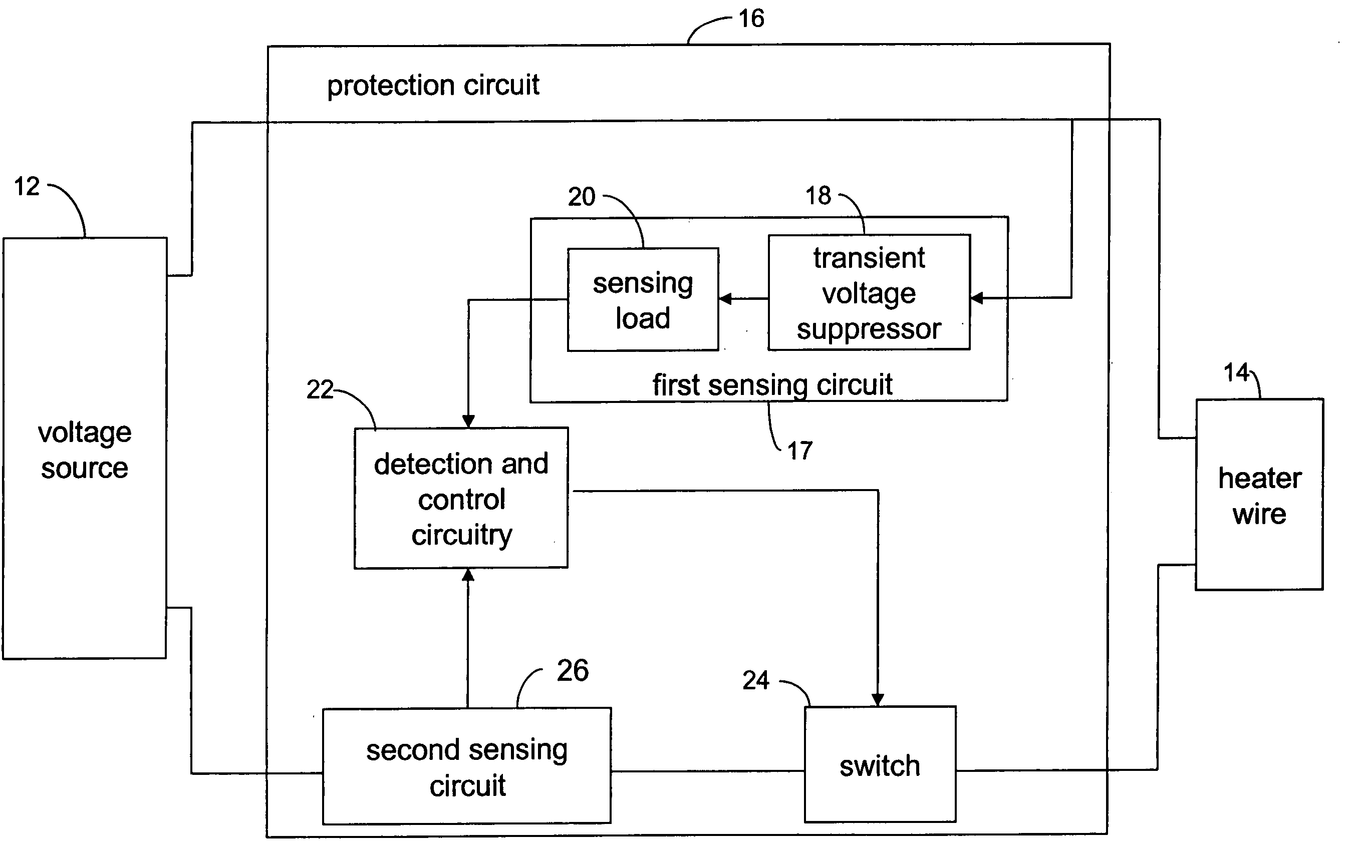
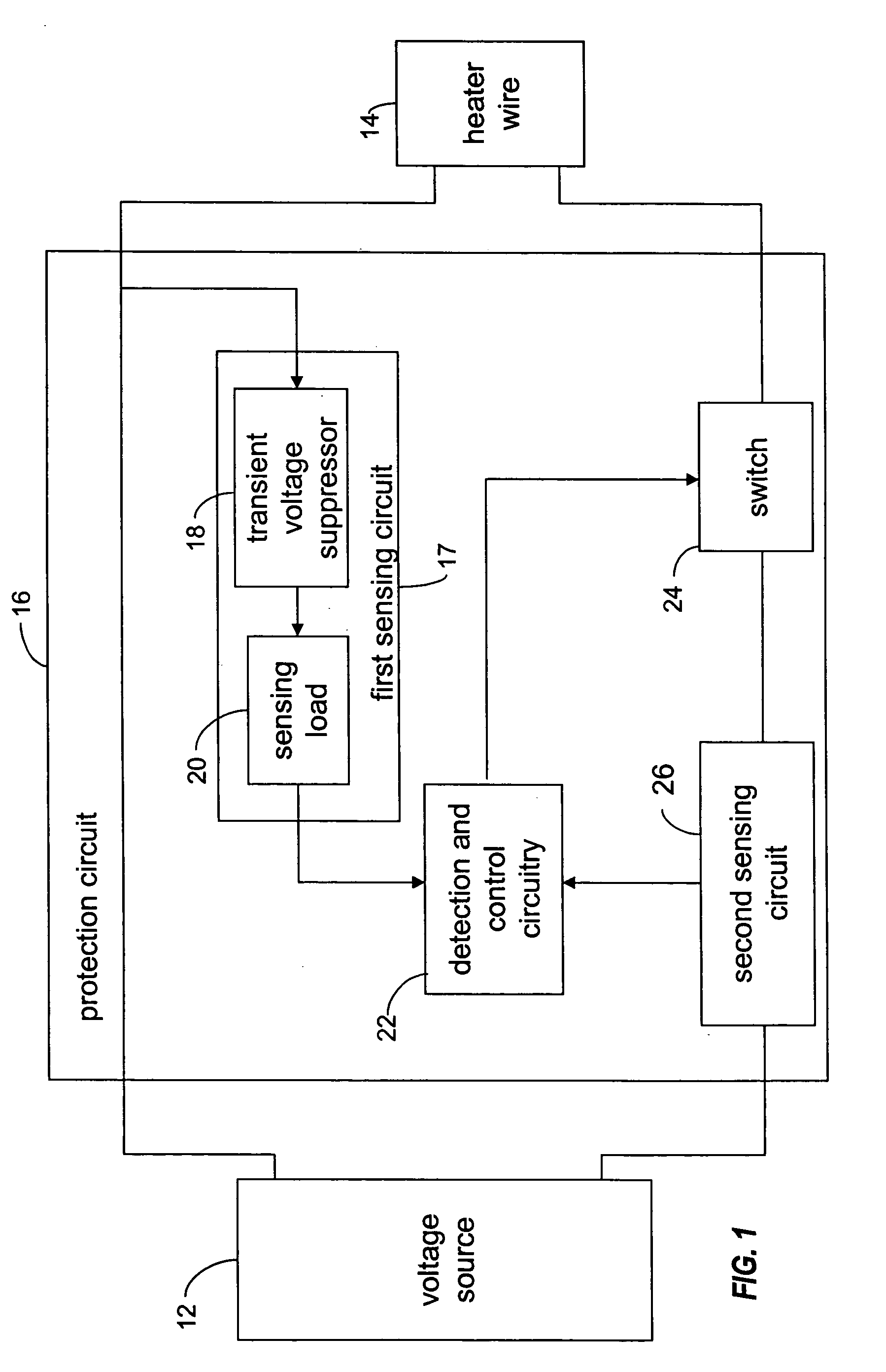
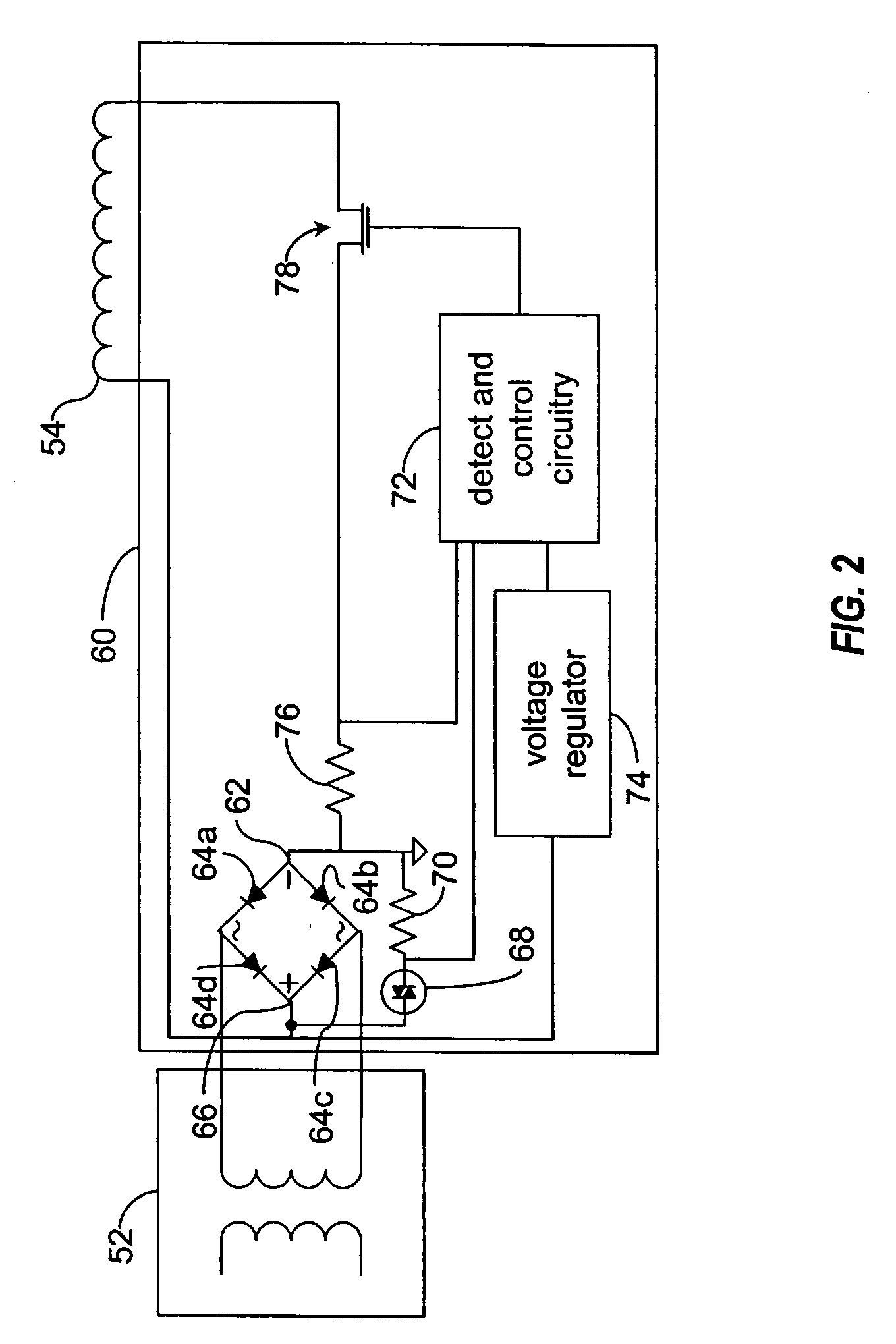
[0011] Power is typically supplied to a humidifier heater circuit via a standard AC supply, and a heater wire is supplied with power from the secondary side of a step-down transformer. According to the present invention, a protection circuit configured to detect an arcing condition, or conditions which can lead to arcing in the humidifier heater circuit, is incorporated into the humidifier circuit. In FIG. 1, a block diagram of one embodiment of an electrical arcing protection circuit 16 is illustrated, wherein the protection circuit 16 is coupled between a voltage source 12 and a heater ...


PUM

PropertyMeasurementUnit
voltageaaaaaaaaaa
voltage levelaaaaaaaaaa
transient voltageaaaaaaaaaa

Abstract

A protection circuit, configured to detect and suppress electrical pre-arcing and arcing conditions in a resistive heater wire circuit, comprises a transient voltage suppressor, signal level sensing load coupled to the output of the voltage suppressor, detection and control circuitry, and a high-speed switch or electrical gate. The control circuitry is configured to control the operation of the switch, coupled between said control circuitry and the heater wire, wherein the switch is opened in response to an electrical pre-arcing or arcing condition or a short circuit condition.

Description

BACKGROUND OF THE INVENTION [0001] 1. Field of the Invention [0002] The present invention relates to a device for preventing or suppressing an electrical pre-arcing condition in a heated respiratory breathing circuit. [0003] 2. Description of the Related Art [0004] Ventilator circuits are designed for directing breathing gas supplied by a ventilator or respirator to a patient. Typically, the breathing gas is humidified by a humidifier cooperating with the respiratory circuit, often located at or near the ventilator or respirator whereby the humidified gas travels along a substantial length of the inspiratory limb of the respiratory circuit. The humidified gas becomes cooled as it travels along the inspiratory tubing resulting in condensation or “rain out” inside the tubing. To prevent such condensation, which otherwise could interfere with the efficiency of the breathing circuit and possible injury to a patient, the circuit may be provided with heater wire extending along the interi...

Claims


Application Information

Patent Timeline
Patent Type & Authority Applications(United States)
IPC IPC(8): G01R31/08G01R31/12H01H9/50
CPCA61M16/1095H02H1/0015
Inventor BOUTON, CHAD E.RUGGERI, FELICIA R.
Owner TELEFLEX MEDICAL INC
Learn More