Adjustable posterior spinal column positioner

a positioner and posterior spinal column technology, applied in the field of adjustable posterior spinal column positioners, can solve the problems of unbalanced axial load of anterior and posterior columns, low back pain, and pain produced by patients,

Active Publication Date: 2006-01-05
DEPUY SPINE INC (US)
View PDF10 Cites 522 Cited by
  • Summary
  • Abstract
  • Description
  • Claims
  • Application Information

AI Technical Summary

Benefits of technology

[0008] The present inventors have developed a number of height-adjustable devices suitable for insertion between posterior processes. These devi

Problems solved by technology

The leading cause of lower back pain arises from rupture or degeneration of lumbar intervertebral discs.
This condition, called “spinal stenosis”, narrows the spinal canal and causes impingement of tissue upon the spinal cord and nearby nerves, thereby producing pain.
However, in some cases of disc replacement, the axial loads borne

Method used


Image

  • Adjustable posterior spinal column positioner
  • Adjustable posterior spinal column positioner
  • Adjustable posterior spinal column positioner

Examples


Embodiment Construction

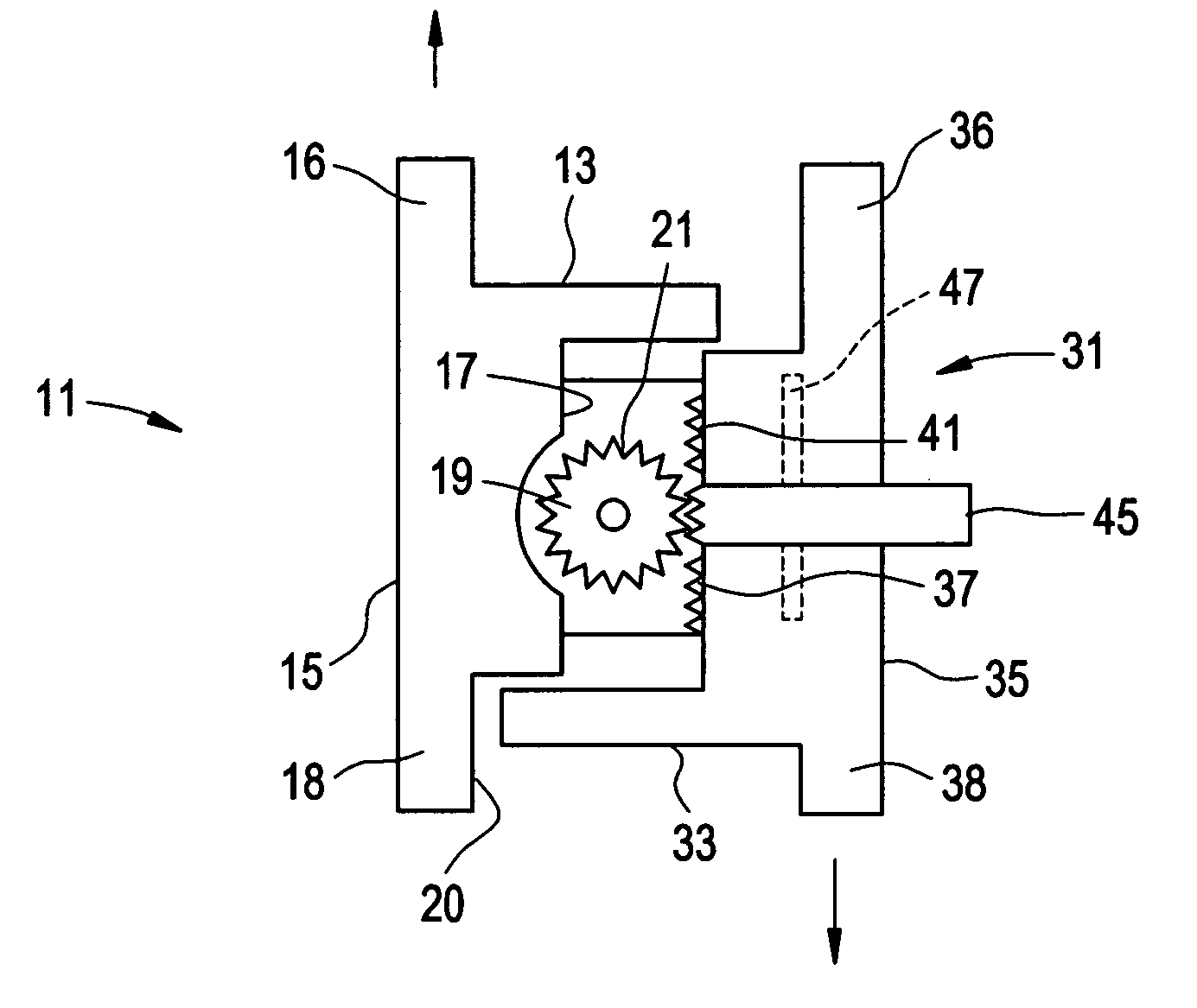
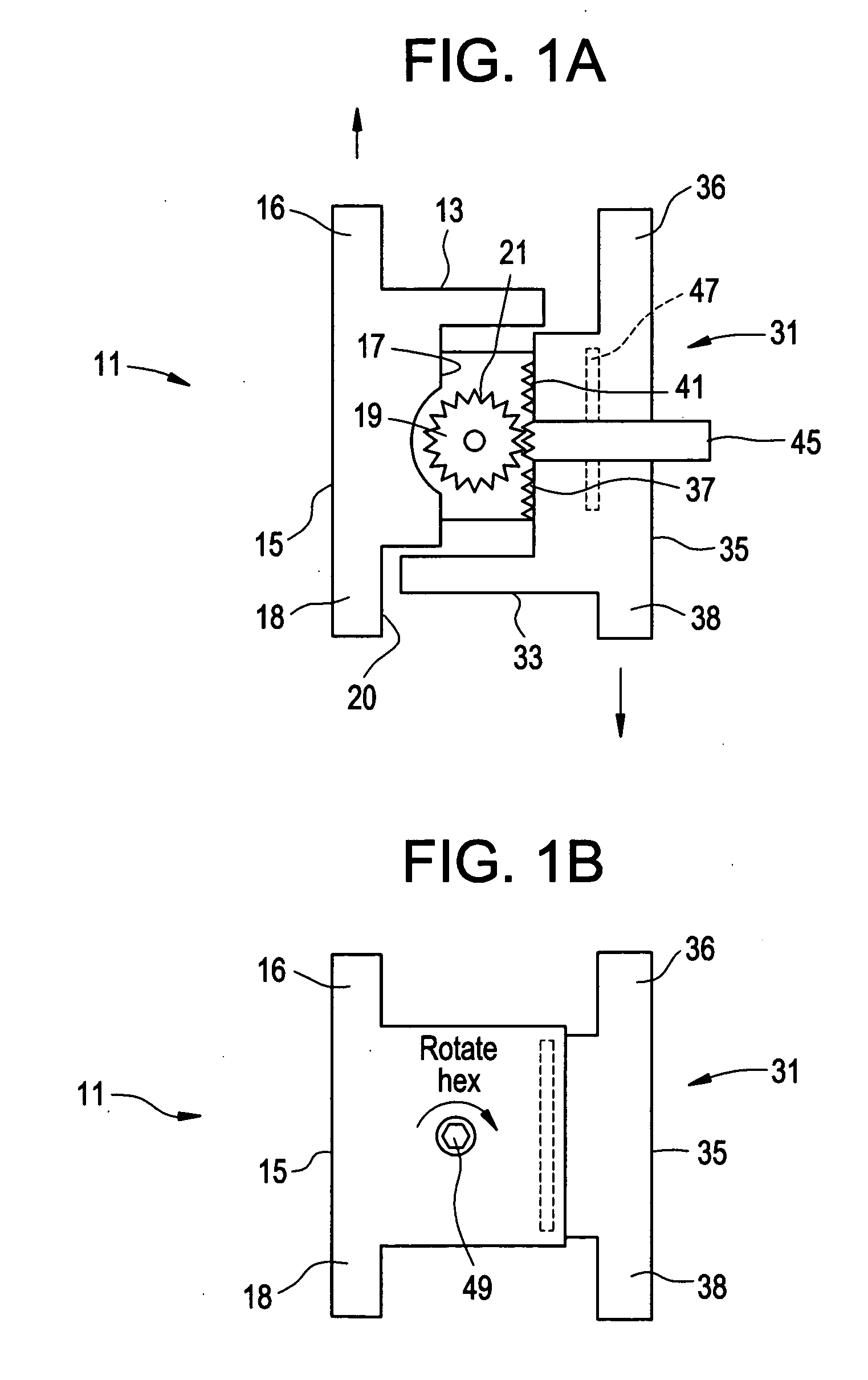
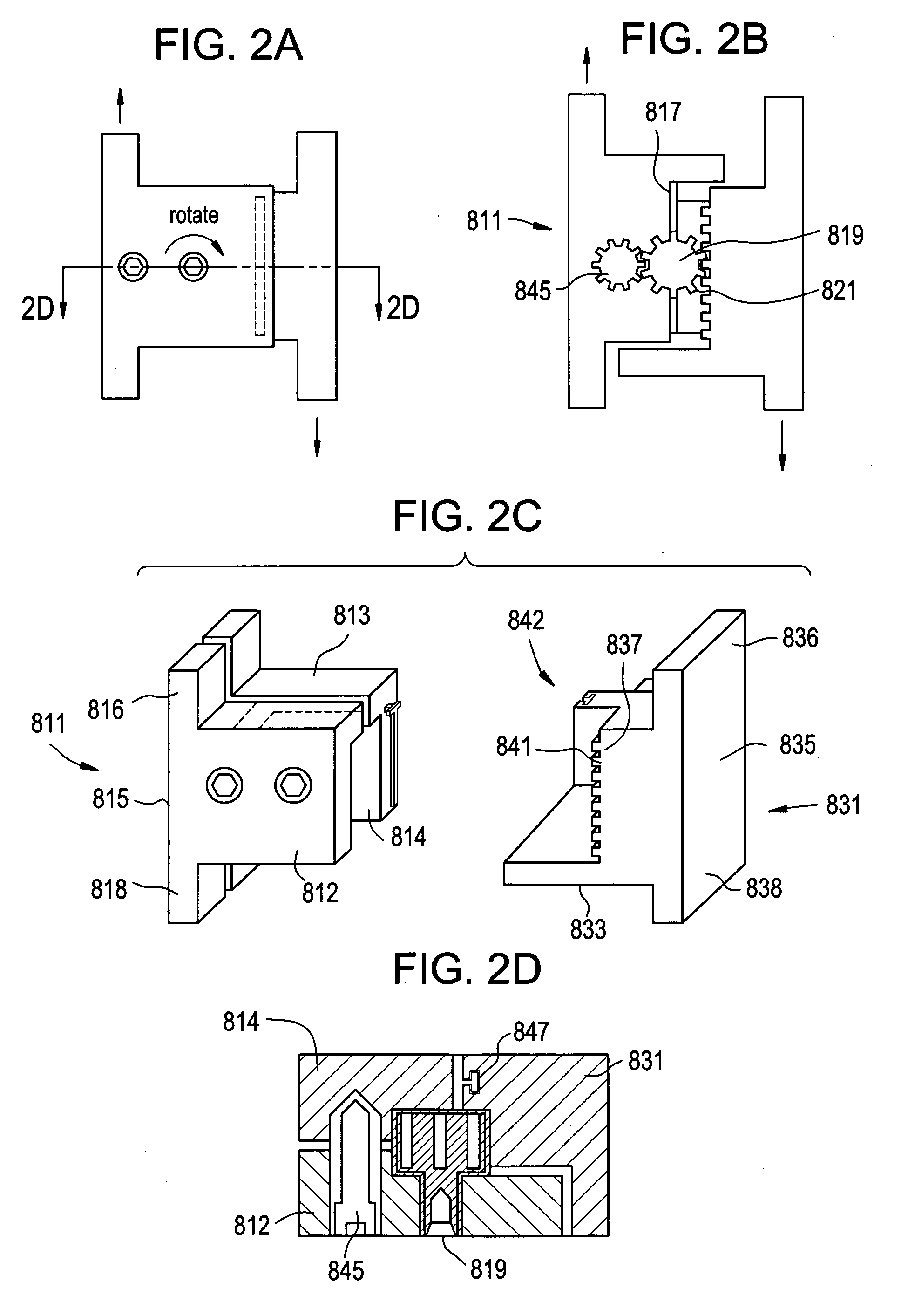
[0035] Referring now to FIGS. 1a and 1b, there is provided an interspinous implant 1 for insertion into an interspinous space between a first and second spinous process, the implant comprising: [0036] a) a first body 11 having: [0037] i. an upper bearing surface 13 for bearing against a first spinous process, [0038] ii. an outer side surface 15 having upper 16 and lower 18 extensions extending therefrom in the axial direction, [0039] iii. an inner surface 17, [0040] iv. a gear 19 attached to the inner surface and having a first set of teeth 21, [0041] b) a second body 31 having: [0042] i. a lower bearing surface 33 for bearing against a second spinous process, [0043] ii. an outer side surface 35 having upper 36 and lower 38 extensions extending therefrom in the axial direction, and [0044] iii. an inner surface 37 having a second set of teeth 41

wherein the upper surface and the lower bearing surfaces define a height of the implant, and wherein the sets of teeth cooperate such that, ...


PUM


Abstract

Height-adjustable devices suitable for insertion between posterior spinal processes that allow the surgeon to post-operatively adjust the height of the implant.

Description

BACKGROUND OF THE INVENTION [0001] The leading cause of lower back pain arises from rupture or degeneration of lumbar intervertebral discs. Pain in the lower extremities is caused by the compression of spinal nerve roots by a bulging disc, while lower back pain is caused by collapse of the disc and by the adverse effects of articulation weight through a damaged, unstable vertebral joint. [0002] In some cases, when a patient having a collapsed disc moves in extension (e.g., leans backward), the posterior portion of the annulus fibrosis or folding of the ligamentum flavum may further compress and extend into the spinal canal. This condition, called “spinal stenosis”, narrows the spinal canal and causes impingement of tissue upon the spinal cord and nearby nerves, thereby producing pain. [0003] The “80 / 20” rule of spine biomechanics postulates that the posterior column of the spine supports about 20% of axial spinal forces. The muscles and ligaments in the posterior column experience t...

Claims


Application Information

Patent Timeline
IPC IPC(8): A61F2/44
CPCA61B17/7065A61B2017/00867A61B2017/00734
Inventor MASTRORIO, BROOKEGIBSON, SHINIKEQUA
Owner DEPUY SPINE INC (US)
Why Eureka
Try Eureka