Seismic image deformation method for improved interpretation

a seismic image and deformation method technology, applied in the field of seismic image deformation, can solve the problems that the characterization of the parameters of geometric transformation remains in some cases a difficult operation

Active Publication Date: 2006-01-05
INST FR DU PETROLE
View PDF10 Cites 26 Cited by
  • Summary
  • Abstract
  • Description
  • Claims
  • Application Information

AI Technical Summary

Problems solved by technology

However, the characterization of the parameters of geometric transformation remains in some cases a difficult operation.

Method used


Image

  • Seismic image deformation method for improved interpretation
  • Seismic image deformation method for improved interpretation
  • Seismic image deformation method for improved interpretation

Examples


Embodiment Construction

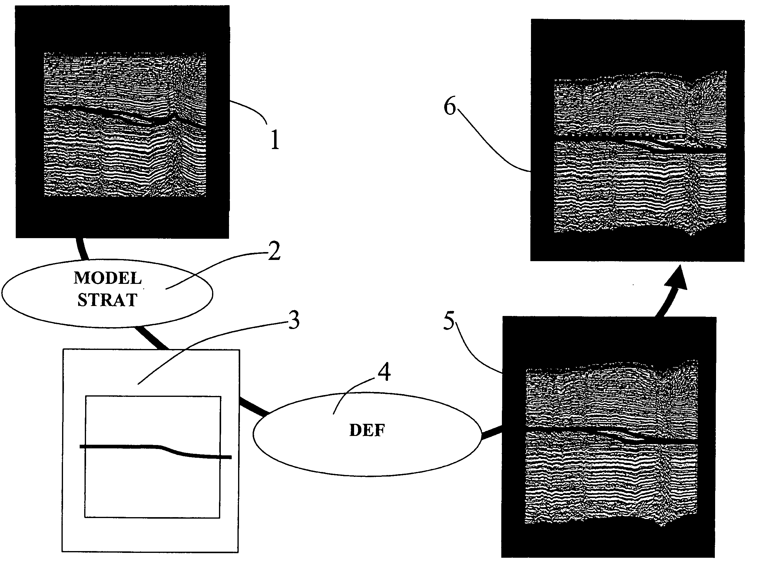
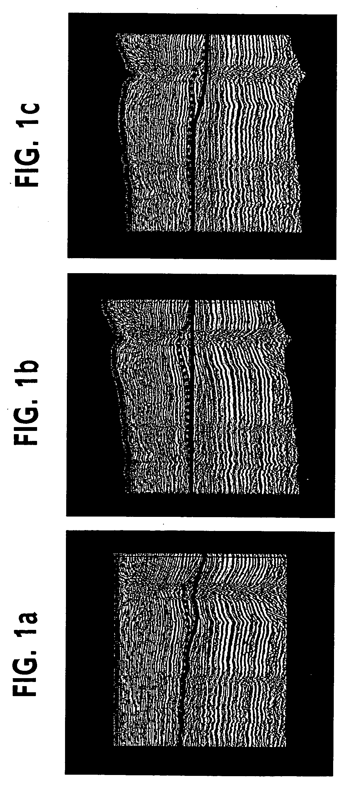
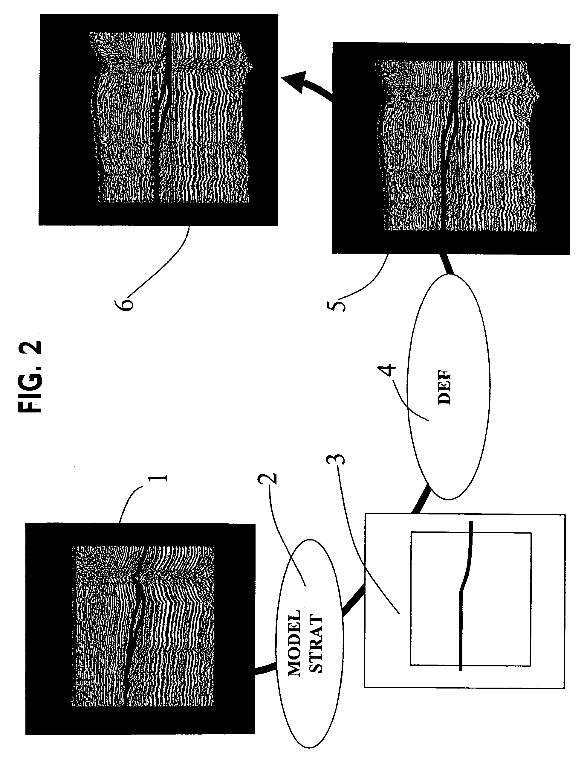
[0030]FIGS. 1a, 1b and 1c illustrate the significance of the present method in relation to the conventional “flattening” method.

[0031]FIG. 1a shows the raw image of a seismic section obtained in a carbonate platform growth environment. The dotted line shows the horizon during picking and its relative position in relation to an earlier deposited surface represented by the full line. It is well known that picking is made difficult by the deformations undergone by the subsoil after deposition of these surfaces. In fact, the image is deformed in relation to what it was at the time of the accumulation of these sediments. This deformation consequently blurs the current geometric structure in relation to the reference scheme of the carbonate platform growth contexts known to the interpreter.

[0032]FIG. 1b shows the same seismic image after “flattening” of the full line representing an earlier deposited surface. The image thus deformed does not represent a geologic reality and it can misle...


PUM


Abstract

The present method relates to a method of geometric deformation of a seismic image for interpretation, comprising the steps of selecting a geologic layer represented in the seismic image; determining by stratigraphic modelling a mean topographic depositional surface for said layer; deforming the seismic image by displacing the traces by taking account of the modelled mean depositional surface, and carrying out a geologic interpretation of the image thus deformed.

Description

BACKGROUND OF THE INVENTION [0001] 1. Field of the Invention [0002] The present invention relates to a method intended for geometric deformation of a seismic image in order to eliminate the effect of the deformations undergone by the subsoil after its deposition. The method applies to the interpretation of seismic sections or cubes. It relates to the geometric deformation of a seismic image (section or cube) in order to make the seismic interpreter's work simpler and to allow easier interpretation control. The data handled are the seismic depth images, cube or section, and characteristic surfaces (or horizons) obtained by picking on the seismic images themselves. Without geometric transformation, these seismic images and these surfaces correspond to a current state of the subsoil and not to its state at the geologic time of deposition of these surfaces. In fact, the subsoil undergoes considerable deformations during the geologic times that follow its deposition. [0003] The method fi...

Claims


Application Information

Patent Timeline
Patent Type & Authority Applications(United States)
IPC IPC(8): G06F19/00G01V1/28
CPCG01V2210/66G01V1/28
Inventor CACAS, MARIE-CHRISTINE
Owner INST FR DU PETROLE
Why Eureka
Try Eureka