Transfer glue system and method for a right angle gluing machine

a transfer glue and right angle technology, applied in the field of transfer glue system and right angle gluing machine, can solve the problems of difficult to obtain satisfactory film-to-film attachment using cold glue, > unusable

Inactive Publication Date: 2006-01-12
GRAPHIC PACKAGING INT
View PDF5 Cites 8 Cited by
  • Summary
  • Abstract
  • Description
  • Claims
  • Application Information

AI Technical Summary

Problems solved by technology

However, it is extremely difficult to obtain a satisfactory film-to-film attachment using cold glue.
Often the presence of a cosmetic flaw will render the erected carrier 190 unusable.

Method used


Image

  • Transfer glue system and method for a right angle gluing machine
  • Transfer glue system and method for a right angle gluing machine
  • Transfer glue system and method for a right angle gluing machine

Examples


Embodiment Construction

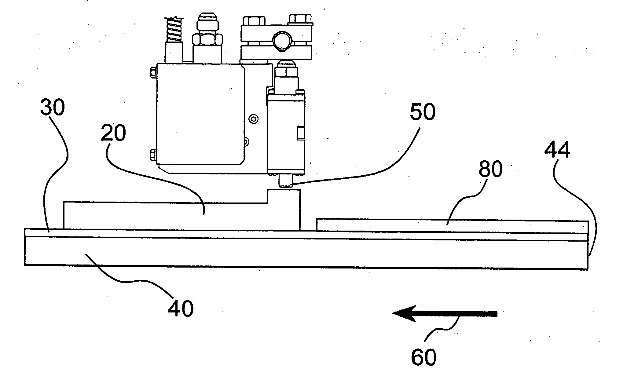
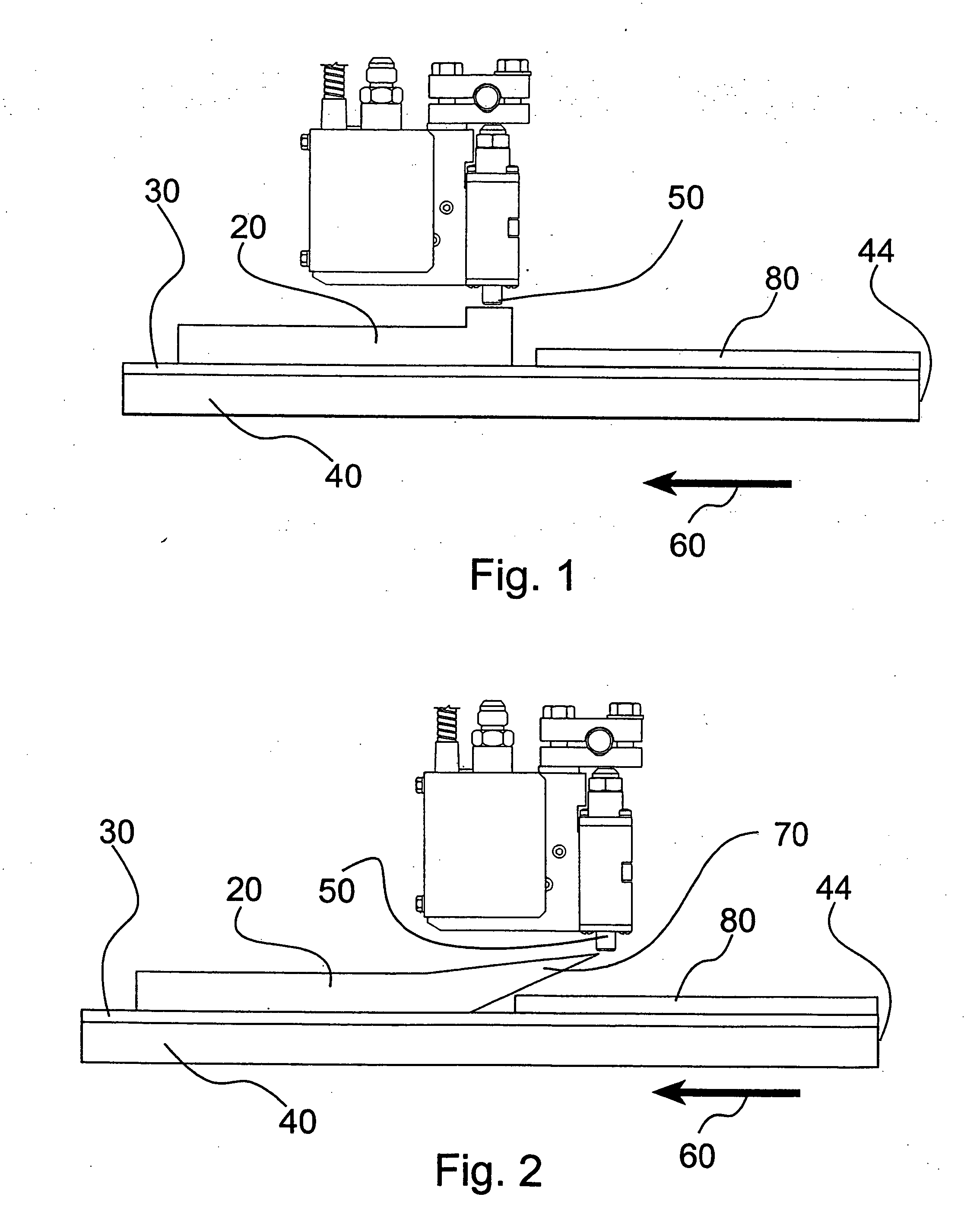
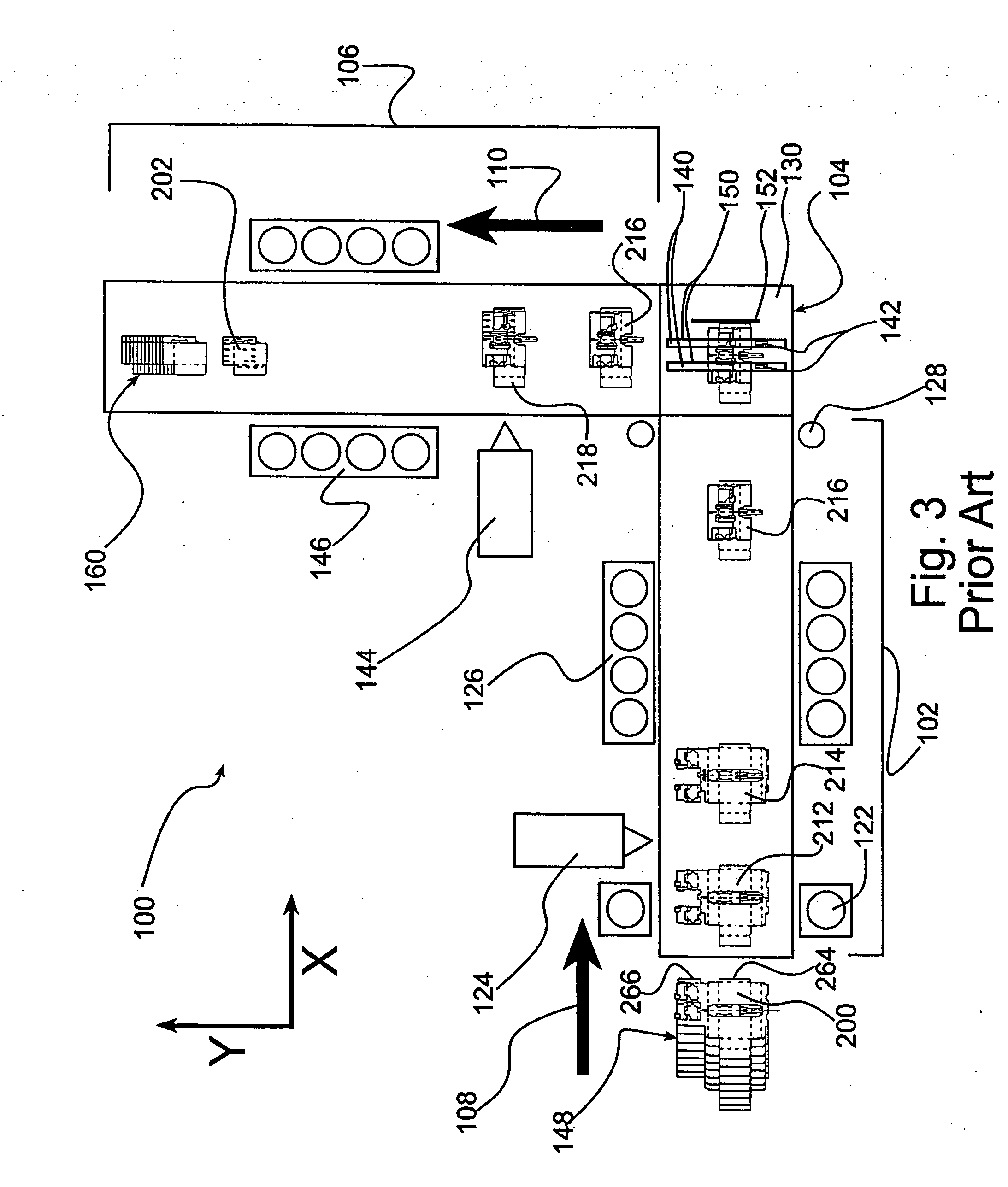
[0079] Referring to FIG. 12, an improved right angle gluing machine 1001 may be provided with a transfer system 600. The transfer system 600 is provided to overcome the limitations of the conventional gluing machine 100 as described previously herein. The transfer system 600 replaces the conventional transfer system 104 of the conventional gluing machine 100 (FIG. 3).

[0080] The improved right angle gluing machine 1001 may be provided with an x-axis subsystem 1020, the transfer system 600 and a y-axis subsystem 1030. The x-axis subsystem 1020 and the y-axis subsystem 1030 of the improved right angle gluing machine 1001 may, for example, be, substantially similar to the conventional x-axis subsystem 102 and the conventional y-axis subsystem 106 of the conventional right angle gluing machine 100. One difference between the conventional y-axis subassembly 106 and the improved y-axis subassembly 1030 is be that the y-axis glue station 144 (FIG. 3) may be omitted in some circumstances.

[...


PUM

PropertyMeasurementUnit
accelerationaaaaaaaaaa
rotational speedaaaaaaaaaa
strengthaaaaaaaaaa

Abstract

Disclosed herein is a method and apparatus for applying adhesive to packaging in a variety of configurations. The adhesive may be applied by a nozzle in a first direction, a second direction and a stationary spot, wherein the first direction and the second direction are transverse to each other.

Description

CROSS-REFERENCE TO RELATED APPLICATIONS [0001] This application is a divisional of co-pending U.S. patent application Ser. No. 10 / 735,534 filed Dec. 12, 2003, which is a divisional of 09 / 877,336 filed Jun. 8, 2001, now U.S. Pat. No. 6,689,034 issued Feb. 10, 2004, for TRANSFER GLUE SYSTEM AND METHOD FOR A RIGHT ANGLE GLUING MACHINE of Walsh et al., both of which are incorporated herein by reference for all that is disclosed therein.FIELD OF THE INVENTION [0002] The present invention is directed towards the field of packaging equipment and packaging construction. BACKGROUND OF THE INVENTION [0003] Once, primarily used to package the aggressive surfactants of concentrated detergents, laminate film packaging is now used for numerous applications including: soap boxes, cereal boxes, bottle carriers, can boxes, etc. The components of laminate film packaging include a layer of printed film and paperboard. The paperboard serves as a substrate to which the film layer is lamimated. The lamin...

Claims


Application Information

Patent Timeline
Patent Type & Authority Applications(United States)
IPC IPC(8): B05B15/02B05C5/00B31B3/00B31B11/00B31B50/62
CPCB31B1/62B31B3/00B31B11/00Y10T156/1798B31B2217/103B31B2241/001B31B2201/6017B31B50/00B31B50/624B31B50/81B31B2105/00B31B2120/20
Inventor WALSH, JOSEPH C.HAWKINS, KENNETH E.
Owner GRAPHIC PACKAGING INT
Why Eureka
Try Eureka