Unmanned air vehicles and method of landing same

a technology of unmanned air vehicles and landing methods, applied in the direction of launching weapons, emergency equipment, floats, etc., can solve the problems of increasing the difficulty of landing, requiring greater sophistication and unique techniques, and severely restricting the number of times that a single vehicle can safely be reused without repair, so as to achieve reliable protection

Active Publication Date: 2006-01-12
ELBIT SYST LTD
View PDF13 Cites 39 Cited by
  • Summary
  • Abstract
  • Description
  • Claims
  • Application Information

AI Technical Summary

Benefits of technology

[0005] It is therefore a broad object of the present invention to ameliorate the disadvantages of the deep stal

Problems solved by technology

While launching such Unmanned Air Vehicles (UAV) is carried out in conventional manners either by means of a runway on which the UAV is propelled to gain sufficient launching speed, or is launched from a base or a short elevated runway or even from an operator's hand, the landing thereof is more problematic and requires greater sophistication and unique techniques.
Utilizing the deep stall landing technique is, however, problem

Method used


Image

  • Unmanned air vehicles and method of landing same
  • Unmanned air vehicles and method of landing same

Examples


Embodiment Construction

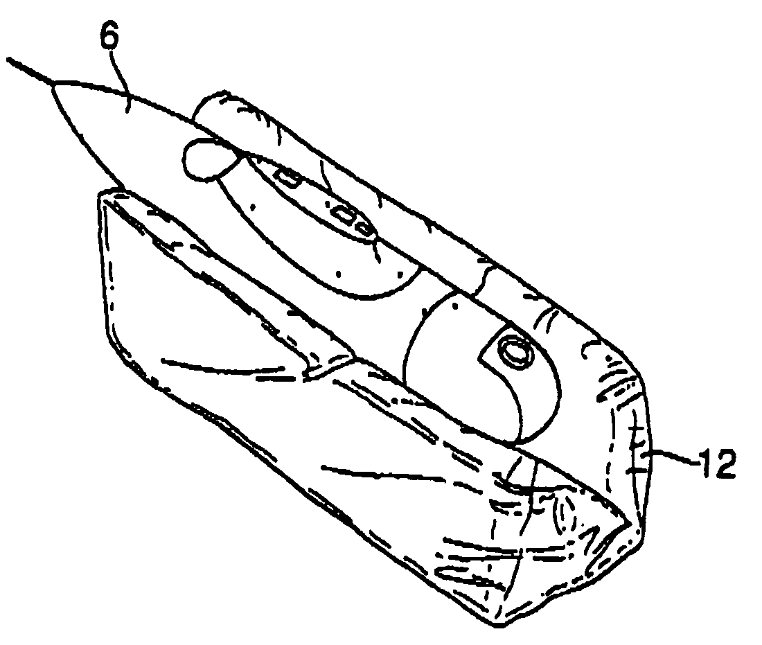
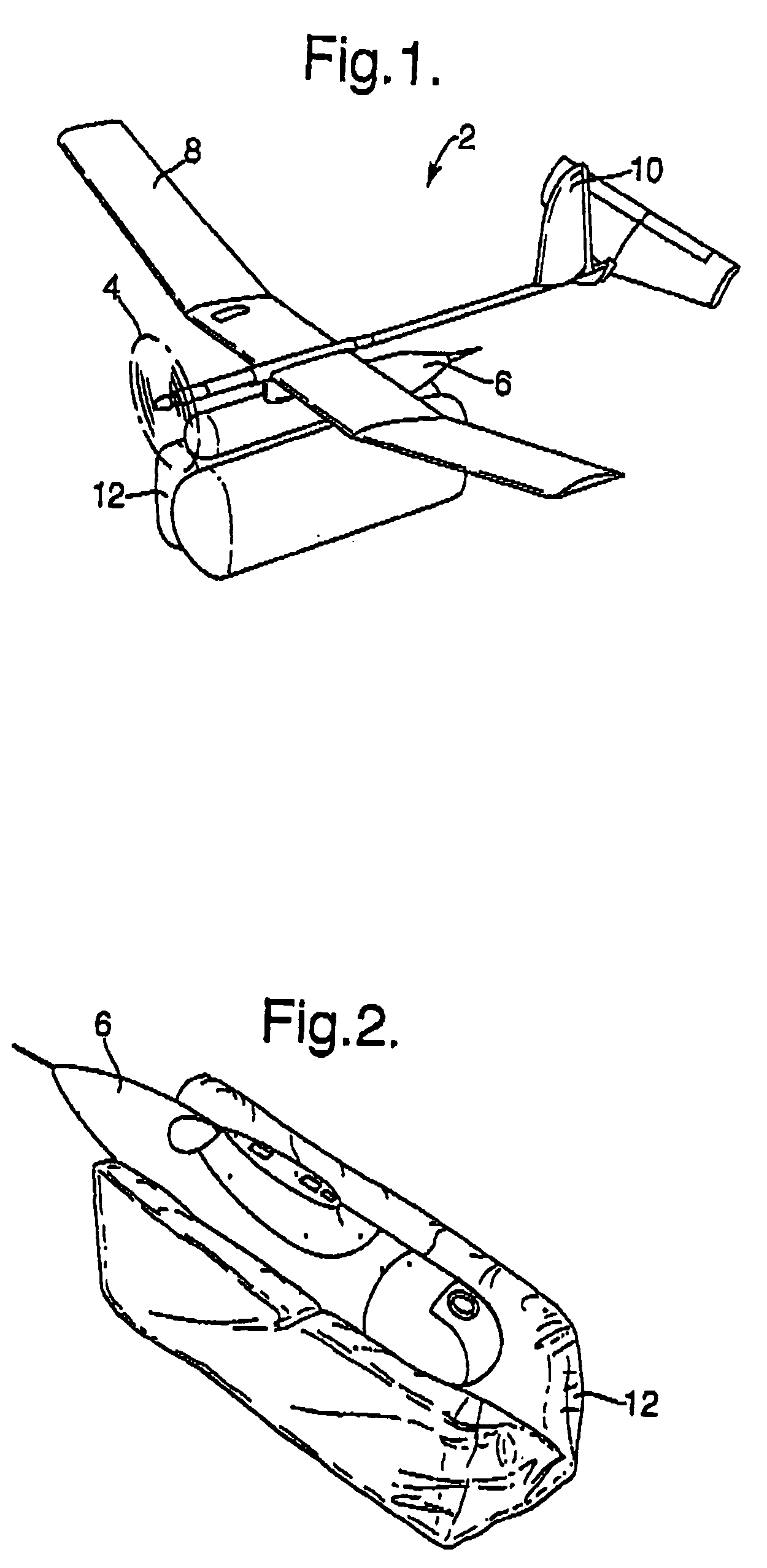
[0017] There is illustrated in FIGS. 1 and 2 a UAV 2 having an engine 4, an airframe 6, wings 8 and a tail assembly 10. The above-described UAV parts may be at least partly integral or assembled in-situ. The engine may be an electric or fuel-operated engine. Further seen is a sleeve 12, advantageously made of durable fabric, attached to the airframe 6. The sleeve 12 may take any desired configuration, e.g., may be substantially prismatic, cylindrical, or as shown, composed of two elongated portions wider than the width of the airframe 6, and advantageously, projecting from the front end of the airframe, when inflated. The sleeve 12 may be integrally connected to the lower surface of the airframe 6, or, alternatively, may be coupled thereto by connecting means provided on both the sleeve and the airframe. In a modification, the sleeve 12 may be provided with means, such as straps and / or hooks, which can be utilized before take-off when preparing the UAV for flight.

[0018] There is fu...


PUM


Abstract

There is provided an Unmanned Air Vehicle (UAV) including an engine and an airframe, including means for performing a deep stall maneouvre; at least one inflatable sleeve connected or connectable to the airframe, and means for inflating the sleeve during flight, wherein the inflated sleeve extends along the lower side of the airframe so as to protect same during deep stall landing. A method for operating an Unmanned Air Vehicle (UAV), including an engine and an airframe is also provided.

Description

FIELD OF THE INVENTION [0001] The present invention relates to unmanned air vehicles and more particularly to the structure of an unmanned air vehicle and a method of landing it. BACKGROUND OF THE INVENTION [0002] While launching such Unmanned Air Vehicles (UAV) is carried out in conventional manners either by means of a runway on which the UAV is propelled to gain sufficient launching speed, or is launched from a base or a short elevated runway or even from an operator's hand, the landing thereof is more problematic and requires greater sophistication and unique techniques. [0003] There are known in the art several methods of landing UAV's. The classic landing is on the vehicle's wheels along a runway. Similar landings are effected with vehicles equipped with skids, sledges or even with reinforced airframes, all necessitating runways or flat clear stretches of land. The per-se known deep stall technique can be applied to any of the above aircraft landing concepts / techniques and equ...

Claims


Application Information

Patent Timeline
IPC IPC(8): B64C25/56B64C39/02
CPCB64C39/024B64C2201/021B64C2201/042B64C2201/044B64C2201/104B64C2201/086B64C2201/167B64C2201/187B64C2201/048B64U50/12B64U50/11B64U70/60B64U50/15B64U70/40B64U10/25B64U30/10B64U50/19
Inventor SIRKIS, OMRI
Owner ELBIT SYST LTD
Why Eureka
Try Eureka