Functionally optimized design of a cylinder liner
A cylinder liner and cylinder technology, applied in the direction of cylinders, cylinder heads, machines/engines, etc., can solve the problems of high design requirements, large-scale use of manufacturing costs, etc.
- Summary
- Abstract
- Description
- Claims
- Application Information
AI Technical Summary
Problems solved by technology
Method used
Image

Examples
Embodiment Construction
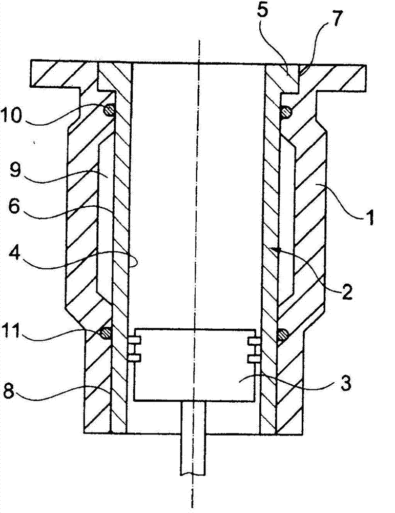
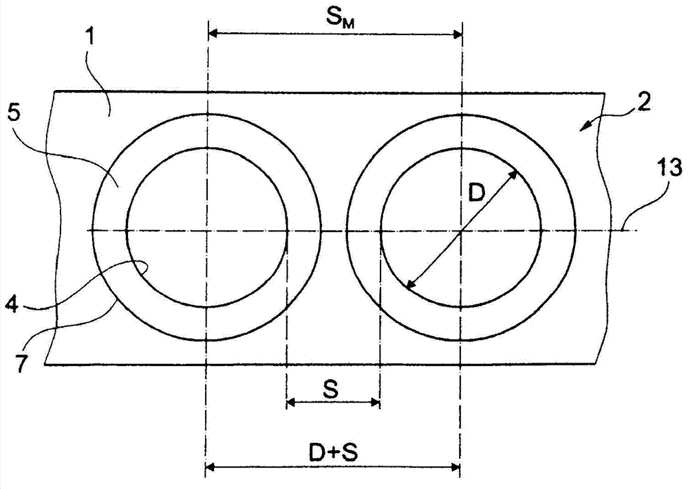
[0028] figure 1 and 2 The construction and installation position of the structure of the known cylinder liner 2 are shown. for this in figure 1 Part of it depicts the cylinder housing 1 , also referred to as the cylinder housing, of the internal combustion engine, which is not shown further. A wet cylinder liner 2 , in which a reciprocating piston 3 is guided on a running surface 4 , is inserted into the cylinder housing 1 , through which the coolant directly circulates. The cylinder liner 2 is fitted into the receptacle 7 or the guide 8 of the cylinder housing 1 with the flange 5 and axially offset therefrom on the outer side 6 . In order to effectively seal off the coolant space 9 , sealing rings 10 , 11 are arranged offset from the flange 5 and in the region of the guide 8 . figure 2 Shows two cylinder liners 2 arranged in the cylinder housing 1 in the direction of the longitudinal axis 13 of the cylinder housing 1 , the center distance S of the two cylinder liners M ...
PUM
 Abstract
Description
Claims
Application Information