Intelligent continuous mining equipment for open-pit mine

An open-pit mine, continuous technology, applied in the field of mining machinery and equipment, can solve the problems of poor processing technology, easy leakage of the system, large size of the reducer, etc., to achieve convenient maintenance and disassembly of equipment, ensure processing technology, and simplify the connection structure. Effect

Pending Publication Date: 2020-10-23
SHANGHAI CHUANGLI GRP
View PDF0 Cites 0 Cited by
  • Summary
  • Abstract
  • Description
  • Claims
  • Application Information

AI Technical Summary

Problems solved by technology

[0002] At present, in the design and application of mining mining equipment, the connection between the main frame body and the rear frame body is mostly connected by flanges. The processing accuracy of the flange surface is strictly required, and the processing technology is not good. When the theoretical size of the distance between the two outer flanges of the main frame body is larger, the processing technology to achieve precise fit is worse, which greatly reduces the installation accuracy of the product.
[0003] In addition, the walking power of existing mining equipment is generally provided by hydraulic motors or excitation motors, and the structure of the walking reducer is relatively scattered, with poor interchangeability, modularization, and low intelligence.
The hydraulic motor transmits power to the hydraulic transmission system. The energy loss is large, the transmission efficiency is low, the system is prone to leakage, and it is difficult to troubleshoot when the system fails. It is sensitive to oil temperature changes. case work
When the excitation motor drives the travel reducer, the efficiency is low, and due to the induced current in the rotor winding, there is rotor resistance and hysteresis loss, which makes the temperature rise, the power factor is low, the reliability is low, and the reducer is large in size
Moreover, the above-mentioned traction method is only suitable for the mining of ore with low hardness underground in small and medium-sized coal mining enterprises, and is not suitable for large-scale and extra-large open-pit coal mining enterprises.

Method used


Image

  • Intelligent continuous mining equipment for open-pit mine
  • Intelligent continuous mining equipment for open-pit mine
  • Intelligent continuous mining equipment for open-pit mine

Examples


Embodiment Construction

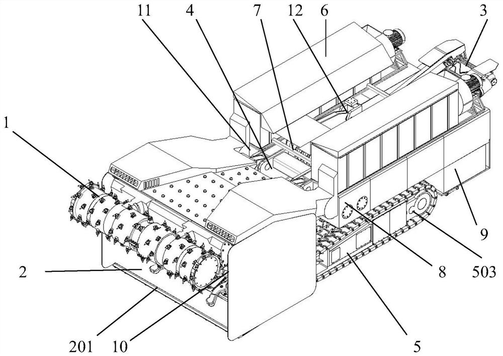
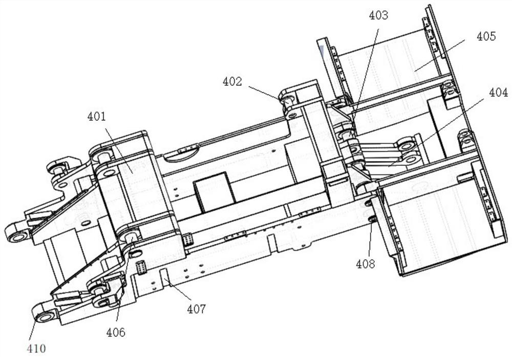
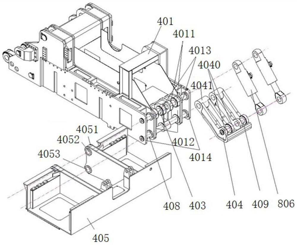
[0044] Such as figure 1 As shown, it is a schematic diagram of the open pit intelligent continuous mining equipment of the embodiment of the present invention, consisting of figure 1 It can be seen that the open pit intelligent continuous mining equipment of the embodiment of the present invention includes a frame part 4 and a walking part 5, and the frame part 4 includes a main frame body 401, a rear frame body 405 and a connecting main frame body 401, a rear frame body 405 connecting device, the running part 5 is installed on the bottom of the frame part 4.

[0045] Specifically, the open-pit intelligent continuous mining equipment of the embodiment of the present invention includes a frame part 4 that is used as a basic support component of the whole equipment and connects other parts into a whole, and is installed on the lower part of the frame part 4 for driving. Equipped with walking part 5 for walking. In addition, the equipment of the embodiment of the present invent...


PUM


Abstract

The invention discloses intelligent continuous mining equipment for an open-pit mine. The intelligent continuous mining equipment comprises a rack part and a traveling part; the rack part comprises amain frame body, a rear frame body and a connecting device for connecting the main frame body with the rear frame body; the traveling part is mounted on the lower part of the rack part; and the connecting device comprises a first connecting structure, a second connecting structure and a third connecting structure, wherein the first connecting structure is used for rotationally connecting the mainframe body with the upper part of the rear frame body and rotationally connecting the main frame body with a pair of rear supporting oil cylinders of a hydraulic part at a time, the second connectingstructure is used for rotationally connecting the main frame body with the lower part of the rear frame body and rotationally connecting the main frame body with a supporting device at a time, and thethird connecting structure is used for connecting the supporting device with the rear supporting oil cylinders to enable the supporting device to conduct corresponding supporting or retraction alongwith extending and retracting of the rear supporting oil cylinders. According to the intelligent continuous mining equipment for the open-pit mine in the embodiment, the main frame body, the rear frame body and the supporting device are connected together at a time through the connecting device, connecting is rapid and convenient, and the structure of the rack part is optimized.

Description

technical field [0001] The invention relates to the technical field of mining machinery and equipment, in particular to intelligent continuous mining equipment for open-pit mines. Background technique [0002] At present, in the design and application of mining mining equipment, the connection between the main frame body and the rear frame body is mostly connected by flanges. The processing accuracy of the flange surface is strictly required, and the processing technology is not good. When the theoretical size of the distance between the two outer flanges of the main frame body is larger, the processing technology to achieve precise fit is worse, which greatly reduces the installation accuracy of the product. . [0003] In addition, the travel power of existing mining equipment is generally provided by hydraulic motors or excitation motors. The structure of the travel reducer is scattered, the interchangeability is poor, and the degree of modularization and intelligence is ...

Claims


Application Information

Patent Timeline
Patent Type & Authority Applications(China)
IPC IPC(8): E21C47/02E21C35/22E21C29/22F15B21/041F15B21/0423
CPCE21C29/22E21C35/22E21C47/02F15B21/041F15B21/0423
Inventor 赵立峰万理想
Owner SHANGHAI CHUANGLI GRP
Why Eureka
Try Eureka