Winch and winch drum

a winch and winch technology, applied in the field of winches and winch drums, can solve the problems of prone to variations, random arrangement of relatively, and premature rope wear, and achieve the effect of reducing rope and preventing snagging of rope on corners

Inactive Publication Date: 2006-01-12
LEWMAR LTD
View PDF76 Cites 1 Cited by
  • Summary
  • Abstract
  • Description
  • Claims
  • Application Information

AI Technical Summary

Benefits of technology

[0013] Preferably, the present invention also aims to guide the rope around the drum in such a way as to avoid bunching of the rope loops at the top of the drum when the rope is being fed down the. drum during rope release.
[0021] Preferably, each channel has a concave shape. The smooth nature of the channels reduces rope wear resulting from sharp edges and prevents snagging of the rope on corners.
[0024] Preferably, the ridges and ribs define a regular axially staggered pattern of depressions. The depressions may tessellate to cover substantially all of the rope-receiving surface of the drum. A regular surface allows increased control because the surface grips in a uniform way.
[0027] This configuration may give the channel a substantially zigzag shape. Therefore, in use, a rope wound around the drum preferably experiences mechanical pushing forces from the ridge elements. The zigzag shape dictates that more rope must contact the surface of the drum in a given rope loop, thereby further improving grip.
[0030] The ridges may project further from the surface of the drum than the ribs. The ridges may provide mechanical gripping (e.g. through making the rope deviate) whereas the ribs may provide frictional gripping (e.g. by biting into the rope). Thus, it may be preferable to keep the height of the ribs small to prevent excess rope wear.
[0032] The inventors have found that this arrangement can advantageously assist in reducing rope wear. In particular, the first (smooth) portion may be located at the part of the drum onto which the rope is guided from the load. Typically, that is normally the lower end of the drum in use.

Problems solved by technology

However, because a given finish will usually cause rope wear, in practice the choice of a particular finish for a given application will often represent a compromise between grip and wear.
Both processes result in a random arrangement of relatively fine (in relation to the dimensions of the drum) peaks and dents on the grip surface of the winch drum.
Peened finishes provide good gripping characteristics and controlled letting-off of rope from the winch drum, but have a tendency to promote premature rope wear.
That is, peened finishes are susceptible to variations caused by e.g. changes to the velocity and direction of the shot particles.
Subsequent processing can also affect the finish.
Thus there are many factors which can make it difficult to maintain the reproducibility of peened finishes.
It is also difficult to quantify the essential parameters of any particular finish (meaning those parameters which determine grip and wear) because of the essentially random nature of the arrangement of peaks and dents.
This can be a particular disadvantage if it is desired to investigate systematically the effects of different finishes on rope grip and rope wear, e.g. by varying systematically the parameters of the finish.
However, the grip provided by this type of finish tends to be too strong so that when controlled release of the rope is attempted from the winch, large quantities of rope are let off at a time rather than an even, slow feed-off.
The machining process for providing the pyramidal protuberances is very complex, requiring generated shapes.
This requires a significant amount of programme and machine software processing time, and modern,. complex machines.

Method used


Image

  • Winch and winch drum
  • Winch and winch drum
  • Winch and winch drum

Examples


Embodiment Construction

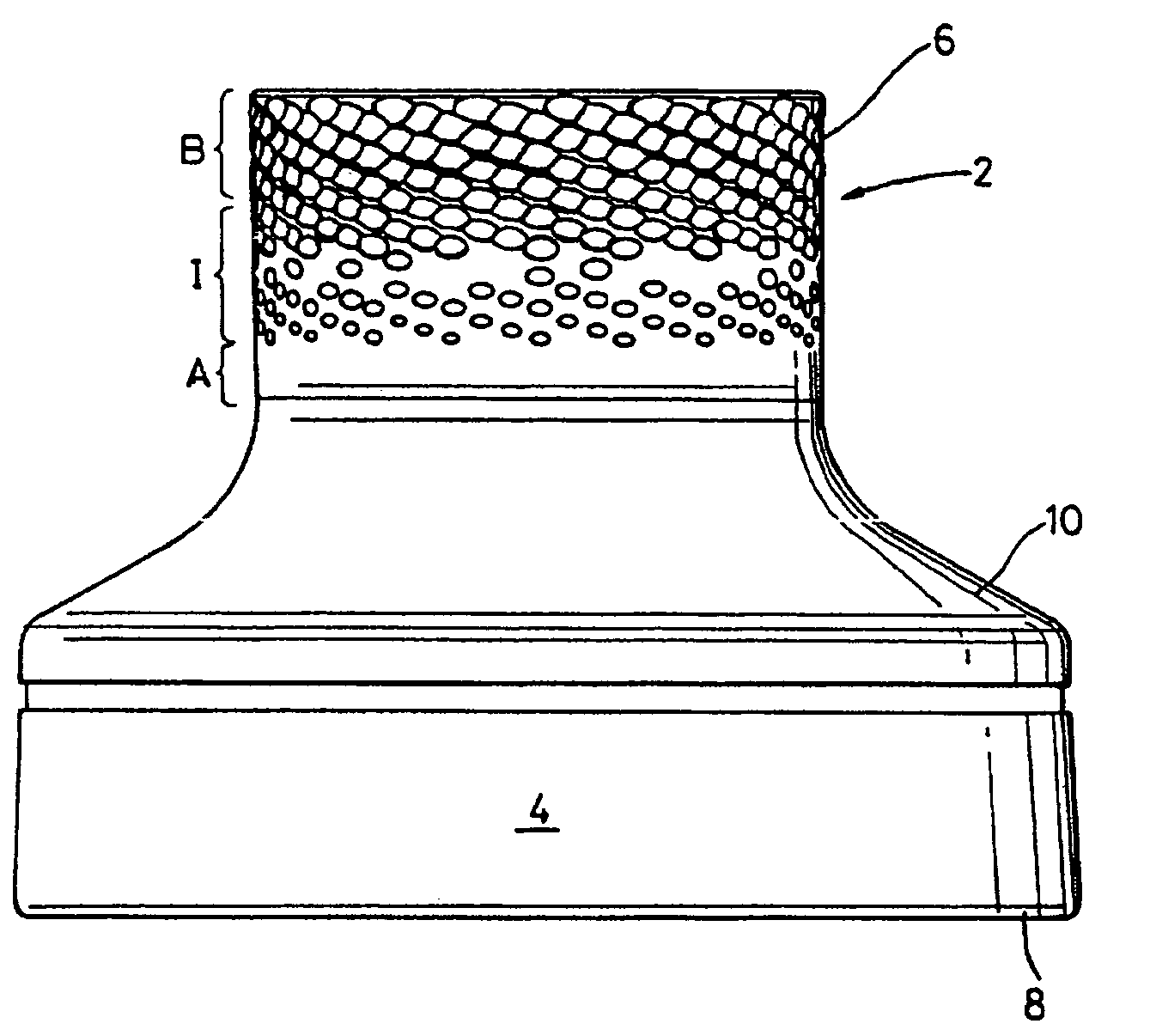
[0041]FIG. 1 shows a winch drum 2 for rotatable mounting on a winch (not shown), the winch drum having a skirt 4 and a rope-gripping surface 6 positioned axially above a lower lip 10. In use, assembled on a winch, an upper lip part of the winch would be positioned axially above the winch drum. The rope-gripping surface is essentially cylindrical, of modified circular cross- section.

[0042] In use, a winch incorporating the winch drum 2 is secured by its base to a surface such as the deck of a yacht with the axis of rotation of the drum perpendicular to the surface, and a rope is wound around the rope- gripping surface, in single or (preferably) multiple loops, the lips preventing the rope from riding axially off the surface 6. Drive to rotate the drum can be applied from the head of the winch (not shown), or from below the deck in a known manner.

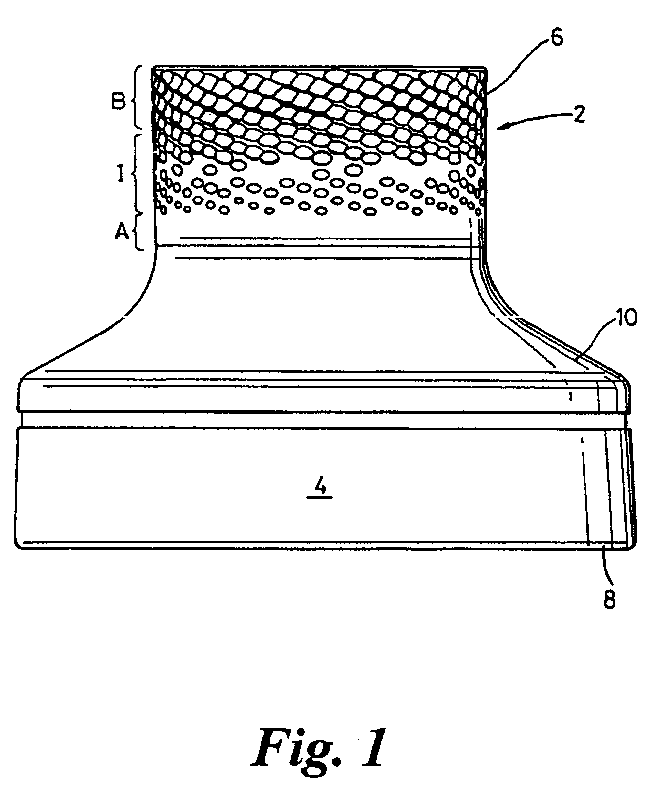
[0043] The surface 6 of the upper portion of the drum has a finish which is shown in more detail in FIG. 2. The surface finish comprises h...


PUM


Abstract

Disclosed is a winch drum for rotation about a rotation axis. The winch drum has a rope-receiving surface with a plurality of raised ridges defining substantially helical channels between them. The channels provide guidance for rope along the rope-receiving surface at least during rope release. The ridges have a meandering shape extending around the drum, formed from a series of alternating circumferential and axially inclined ridge elements.

Description

[0001] This application claims priority from pending Great Britain application number 0409253.2 filed Apr. 26, 2004. FIELD OF THE INVENTION [0002] The present invention relates to winches and winch drums, for example for use on sailboats such as yachts. Of particular interest are surface finishes of such winches and winch drums. RELATED ART [0003] Winches are commonly used in marine applications to control the length of or tension in a rope wound on the rotatable drum of the winch. An important feature of the winch drum of such a winch is the finish applied to the rope-gripping surface of the drum. Different types of finish produce different grip characteristics. However, because a given finish will usually cause rope wear, in practice the choice of a particular finish for a given application will often represent a compromise between grip and wear. [0004] One known finish for a metallic winch drum is provided by shot-peening. In this process, ceramic grit shot particles are directed...

Claims


Application Information

Patent Timeline
Patent Type & Authority Applications(United States)
IPC IPC(8): B66D1/00B66D1/30B66D1/74
CPCB66D1/7494B66D1/7421
Inventor COBDEN, TONYTREAGUST, CHRISTOPHER LESLEY
Owner LEWMAR LTD
Why Eureka
Try Eureka