Thermal transfer printer

a technology of thermal transfer printer and thermal transfer ribbon, which is applied in the field of thermal transfer printer, can solve the problems of large residual quantity, inability to accurately calculate residual quantity, and increase in so as to achieve accurate calculation of residual quantity of ink ribbon and increase the cost of ink ribbon

Inactive Publication Date: 2006-01-12
FUNAI ELECTRIC CO LTD
View PDF3 Cites 62 Cited by
  • Summary
  • Abstract
  • Description
  • Claims
  • Application Information

AI Technical Summary

Benefits of technology

[0008] To solve the above-mentioned problems, the present invention intends to provide a thermal transfer printer capable of perform normal printing by grasping residual quantity of an ink ribbon accurately and locating the start of an unused region of the ink ribbon.
[0012] According to the invention, since the used information is recorded in the mark pattern formed on the ink ribbon, even when the ink ribbon intentionally wound back by the user is loaded, before image formation, the start of the unused region can be located and normal printing can be performed. Furthermore, by counting the used information read by the optical sensor, residual quantity of the ink ribbon can be calculated accurately. Still furthermore, since the used information is recorded in the first mark pattern for alignment, which is originally formed on the ink ribbon, no increase in cost of the ink ribbon occurs.

Problems solved by technology

However, since thickness of the ink ribbon is very thin in the thermal transfer printer in which the outer diameter of the feed roll is measured, an error of the residual quantity calculated based on the outer diameter becomes large and thus residual quantity cannot be calculated accurately.
Furthermore, the printer in which the residual quantity data formed on the ink ribbon is read has a problem of causing increase in cost of the ink ribbon.
In such thermal transfer printer, however, for example, when the ink ribbon is detached after printing images several times and replaced with another used ink ribbon, residual quantity of the ink ribbon cannot be grasped accurately.
As a result, normal printing cannot be ensured.
In such a thermal transfer printer, provision of the transparent heat-sensitive zone in the ink ribbon necessarily causes increase in cost of the ink ribbon.

Method used


Image

  • Thermal transfer printer
  • Thermal transfer printer
  • Thermal transfer printer

Examples


Embodiment Construction

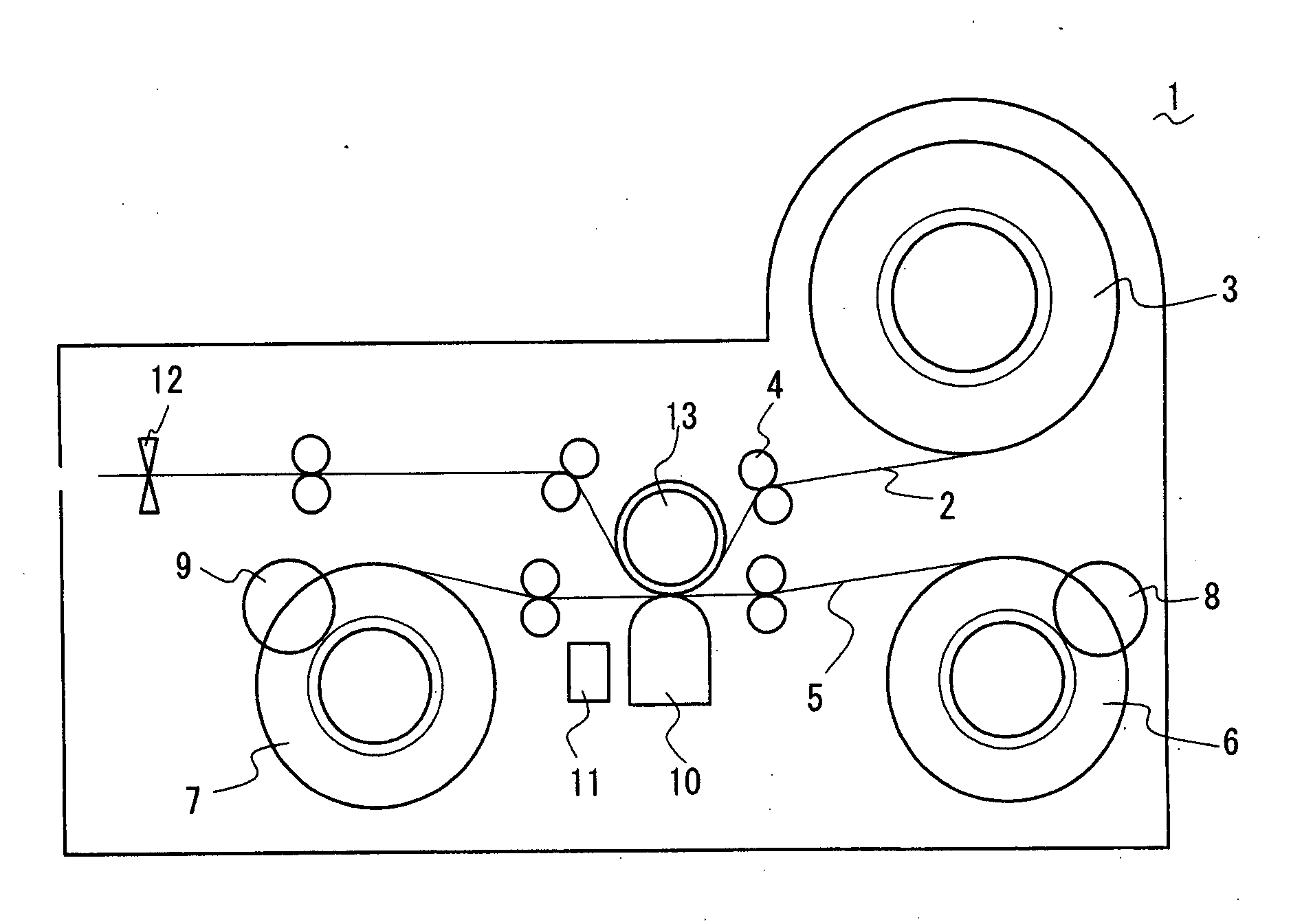
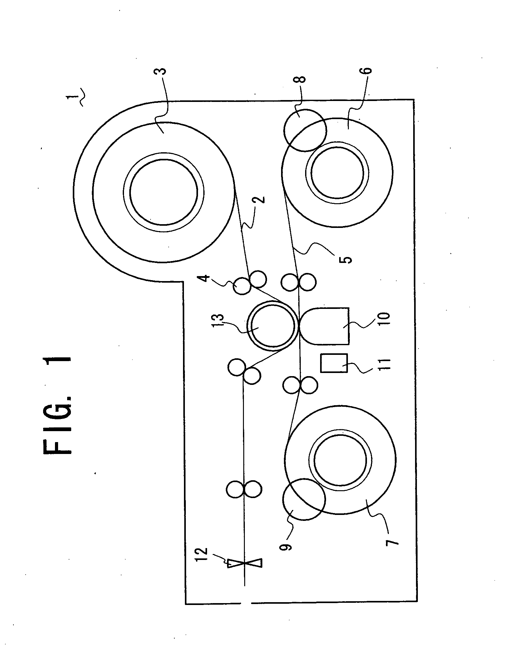
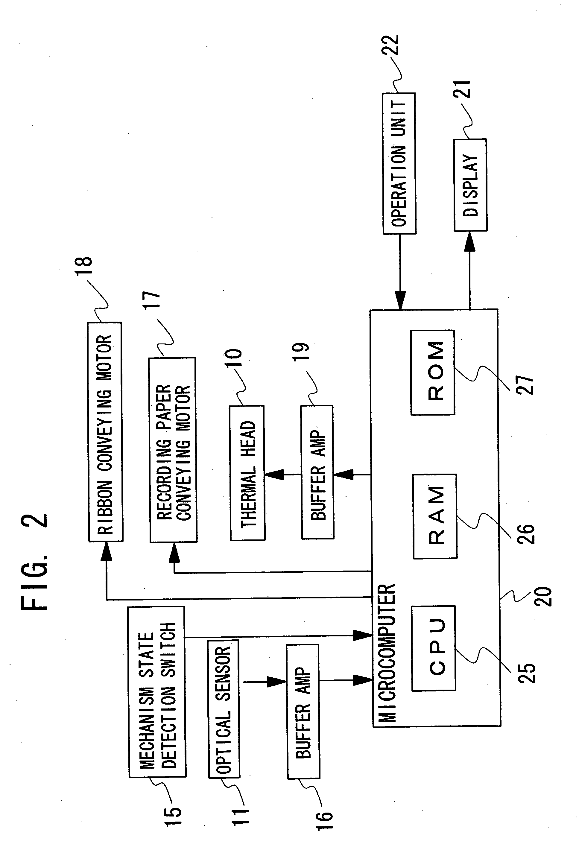
[0019] A thermal transfer printer in accordance with a preferred embodiment for carrying out the present invention will be described with reference to figures. FIG. 1 schematically shows a mechanical configuration of a thermal transfer printer in accordance with the embodiment and FIG. 2 shows an electrical configuration of the thermal transfer printer.

[0020] The thermal transfer printer (hereinafter, referred to as a printer) 1 is comprised of a recording paper roll 3 formed of a long recording paper 2 wound around a cylindrical core, a recording paper conveying mechanism 4 for conveying the recording paper 2 sent from the recording paper roll 3 in its longitudinal direction, a feed roll 6 and a take-up roll 7 around which a long ink ribbon 5 on which an ink component is applied is wound, ink ribbon drive mechanisms 8 and 9 for rotationally driving the feed roll 6 and take-up roll 7, a thermal head 10 for thermally transferring the ink component of the ink ribbon 5 to form an imag...


PUM


Abstract

In a thermal transfer printer, before a thermal head transfers an ink component of a yellow region on a recording paper, the thermal head is preheated up to a transfer temperature and by sublimating a black ink component constituting a mark pattern during preheating, records used information in the mark pattern. After turn-on of an electric power, when an optical sensor reads the used information, an ink ribbon driving mechanism is driven until the optical sensor detects the rear mark pattern in which the used information is not recorded to locate the start of an unused region of an ink ribbon. Thus, residual amount of the ink ribbon is grasped accurately and the start of the unused region is located accurately without increasing the costs of ink ribbon.

Description

BACKGROUND OF THE INVENTION [0001] 1. Field of the Invention [0002] The present invention relates to a thermal transfer printer for thermally transferring an ink applied on an ink ribbon on a recording paper. [0003] 2. Description of Related Art [0004] Conventionally, in thermal transfer printers, to inform the user of the need for changing an ink ribbon soon, various mechanisms for detecting residual quantity of the ink ribbon have been studied. For example, a thermal transfer printer in which residual quantity of the ink ribbon is calculated by measuring the outer diameter of a feed roll has been proposed. A thermal transfer printer in which residual quantity data indicating residual quantity is formed on the ink ribbon in advance and the residual quantity data is read by an optical sensor or the like has been also proposed. [0005] However, since thickness of the ink ribbon is very thin in the thermal transfer printer in which the outer diameter of the feed roll is measured, an er...

Claims


Application Information

Patent Timeline
Patent Type & Authority Applications(United States)
IPC IPC(8): B41J17/28
CPCB41J17/36B41J2/325
Inventor UEDA, HIDEO
Owner FUNAI ELECTRIC CO LTD
Why Eureka
Try Eureka