Apparatus and method for cooling electrical equipment

a technology for electrical equipment and apparatus, applied in the field of electrical equipment cooling, can solve the problems of lowering the accuracy of battery cooling control and the inability to accurately grasp the cooling performance of the cooling fan

Active Publication Date: 2009-10-08
TOYOTA JIDOSHA KK
View PDF0 Cites 32 Cited by
  • Summary
  • Abstract
  • Description
  • Claims
  • Application Information

AI Technical Summary

Benefits of technology

[0026]According to the present invention, based on the duty command at the time of controlling the electric motor, it is possible to detect the state of supply of the second supply means. Therefore, by estimating the degree of cooling based on the selected distribution route and the duty command, it is possible to correctly grasp the cooling performance of the first supply means for the electrical equipment.

Problems solved by technology

As a result, it becomes impossible to accurately grasp the cooling performance of the cooling fan only from information related to the state of operation of the cooling fan (such as a duty command value or fan rotation speed).
This possibly leads to lower accuracy of cooling control of the battery, or to a delay in determining an abnormality condition such as an excessive charging of the battery.

Method used


Image

  • Apparatus and method for cooling electrical equipment
  • Apparatus and method for cooling electrical equipment
  • Apparatus and method for cooling electrical equipment

Examples


first embodiment

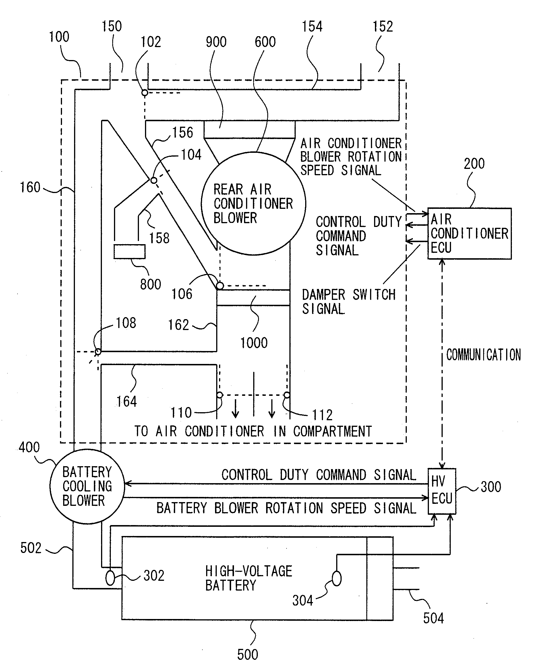
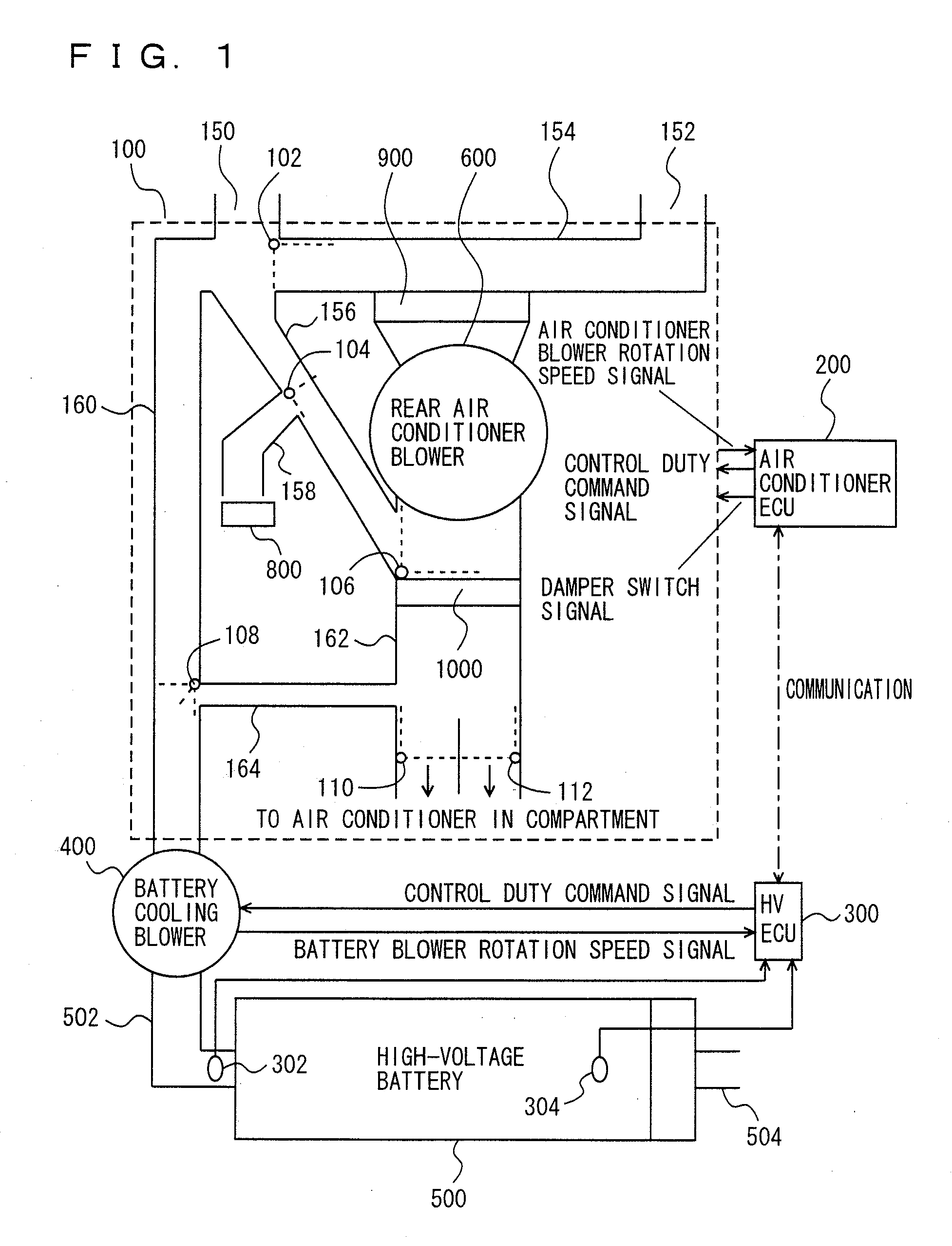
[0042]As shown in FIG. 1, the cooling apparatus for electrical equipment in accordance with the present embodiment includes a rear air conditioner unit 100, an air conditioner ECU (Electronic Control Unit) 200, an HV_ECU 300 and a battery cooling blower 400.

[0043]In the present embodiment, the “electrical equipment” is described as a high-voltage battery 500. The electrical equipment, however, is not specifically limited to the high-voltage battery and it may be a capacitor, a fuel cell, an inverter or other electrical equipment.

[0044]Further, in the present embodiment, high-voltage battery 500 is mounted on a hybrid vehicle having a rotating electric machine and an internal combustion engine as driving sources. High-voltage battery 500 supplies electric power to the rotating electric machine. The vehicle is not limited to a hybrid vehicle and, by way of example, it may be an electric vehicle or a fuel cell vehicle.

[0045]High-voltage battery 500 is mounted between a rear seat provid...

second embodiment

[0137]In the following, a cooling apparatus for electrical equipment in accordance with a second embodiment of the present invention will be described. As compared with the structure of the cooling apparatus for electrical equipment in accordance with the first embodiment described above, the cooling apparatus for electrical equipment in accordance with the present embodiment differs in the tables used for calculating cooling air flow rate Va and cooling performance Wc, and in the structure of flow rate calculating unit 342. Except for these points, it has the same structure as that of the cooling apparatus for electrical equipment in accordance with the first embodiment described above. Therefore, detailed description thereof will not be repeated here.

[0138]The present embodiment is characterized in that HV_ECU 300 receives the state of air supply of rear air conditioner blower 600 and the state of switching of switch dampers 102, 104, 106, 108, 110 and 112 as the route information...


PUM


Abstract

An HV_ECU executes a program, which includes a step of receiving route information; a step of acquiring a duty command value of a battery cooling blower; a step of calculating a cooling airflow; steps for acquiring a battery temperature and an intake temperature; a step of calculating a value TB−TC; a step of calculating a cooling performance; a step of estimating a battery temperature; and a step of performing fail safe processing when in an abnormal state.

Description

TECHNICAL FIELD[0001]The present invention relates to cooling of electrical equipment and, more specifically, to a technique of estimating, with high accuracy, state of supply of cooling medium to electrical equipment connected to a medium passage having a plurality of routes.BACKGROUND ART[0002]Electric vehicles having a motor for running mounted in place of an engine (including vehicles having the motor for running operated by a fuel cell) have been developed and put to practical use. Further, hybrid vehicles having a motor for running mounted in addition to an engine have also been developed and put to practical use. Such a vehicle is provided with a battery for running that outputs driving electric power to the motor for running. The battery for running involves a chemical reaction at the time of charging / discharging and, therefore, it must be cooled to prevent battery degradation caused when the battery attains to a high temperature.[0003]In view of such a problem, Japanese Pat...

Claims


Application Information

Patent Timeline
Patent Type & Authority Applications(United States)
IPC IPC(8): F25D3/00F25D23/00G05D23/00
CPCB60H1/00278B60H2001/003B60H2001/00614G05B9/02H01M10/486H01M10/5095H01M10/5016H01M10/502H01M10/5022H01M10/5024H01M10/5067H01M10/5004H01M10/625H01M10/63H01M10/633H01M10/663H01M10/6563H01M10/635H01M10/613B60L1/003B60L2240/34B60L2240/545B60L2260/44B60L58/33B60L58/26Y02T90/40Y02T10/70Y02E60/10B60L3/0046
Inventor SUZUKI, YUSUKEISHIHARA, TETSUYA
Owner TOYOTA JIDOSHA KK
Why Eureka
Try Eureka