Three-dimensional shape measuring method and device

a three-dimensional shape and measurement method technology, applied in the direction of instruments, optical axis determination, optical apparatus testing, etc., can solve the problems of difficult to acquire the interference fringe corresponding to the entire area of the subject surface using this method, the relative positional relation between the shapes of aspheric lenses is difficult to accurately measure, and the relative positional relation between the shapes is difficult to obtain accurately. , to achieve the effect of accurately acquiring the relative position, and accura

Inactive Publication Date: 2010-09-16
FUJI PHOTO OPTICAL CO LTD
View PDF5 Cites 33 Cited by
  • Summary
  • Abstract
  • Description
  • Claims
  • Application Information

AI Technical Summary

Benefits of technology

[0046]The rotation axis is aligned with the first axis line of the sample top surface or the vertical line at the vertex of the first curved surface (the relative position of the sample and the rotation axis is not changed) while the sample top surface and the outer circumferential surface of the holding jig are being measured. Accordingly, it is possible to accurately acquire the relative position of the sample top surface and the outer circumferential surface of the holding jig on the basis of the position of the rotation axis. Similarly, the rotation axis is aligned with the second axis line of the sample back surface or the vertical line at the vertex of the second curved surface while the sample top surface and the outer circumferential surface of the holding jig are being measured. Accordingly, it is possible to accurately acquire the relative position of the sample back surface and the outer circumferential surface of the holding jig on the basis of the position of the rotation axis.
[0047]The shape of the outer circumferential surface of the holding jig is not variable when it is measured along with the sample top surface and it is measured along with the sample back surface. Accordingly, the first shape information and the second shape information of the outer circumferential surface of the holding jig should be equal to each other in a common coordinate system. Therefore, by combining the first shape information and the second shape information, it is possible to accurately acquire the relative positional relation between the sample top surface and the sample back surface.
[0048]Accordingly, in the second three-dimensional shape measuring method and device according to the invention, it is possible to measure the shapes of the top surface and the back surface of a sample while accurately grasping the relative positional relation therebetween.

Problems solved by technology

However, it is difficult to acquire the interference fringe corresponding to the entire area of the subject surface using this method.
To obtain excellent optical performance, the shapes of aspheric lenses have been complicated.
Specifically, in an aspheric lens having a large number of apertures (NA), the surface misalignment of several pm order or the surface inclination of the order of several tens arc-seconds, which is not considered as a problem, is presently considered as a problem.
The surface misalignment or the surface inclination is also considered as a problem in aspheric lenses (hereinafter, referred to as “polished aspheric lens”) having a high-precision surface shape by a polishing process, not limited to the molded aspheric lenses.
However, in the past shape measuring methods as descried above, the shapes of two lens surfaces could be measured with high precision, but the relative positional relation therebetween could hardly be measured accurately.
However, it is troublesome that another measurement is performed in addition to the measurement of the lens surface shape and much time is taken for the measurement.

Method used


Image

  • Three-dimensional shape measuring method and device
  • Three-dimensional shape measuring method and device
  • Three-dimensional shape measuring method and device

Examples


first embodiment

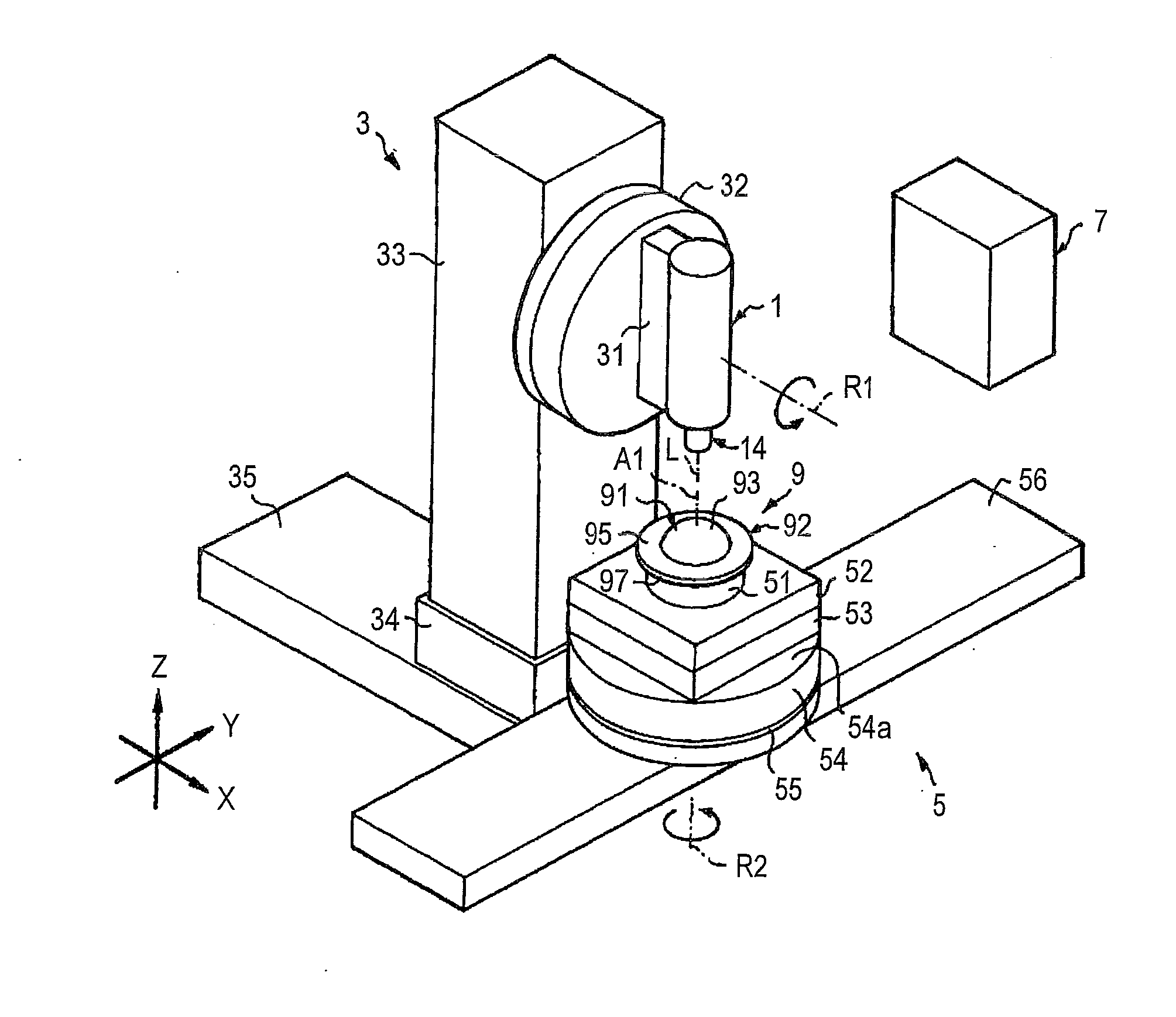
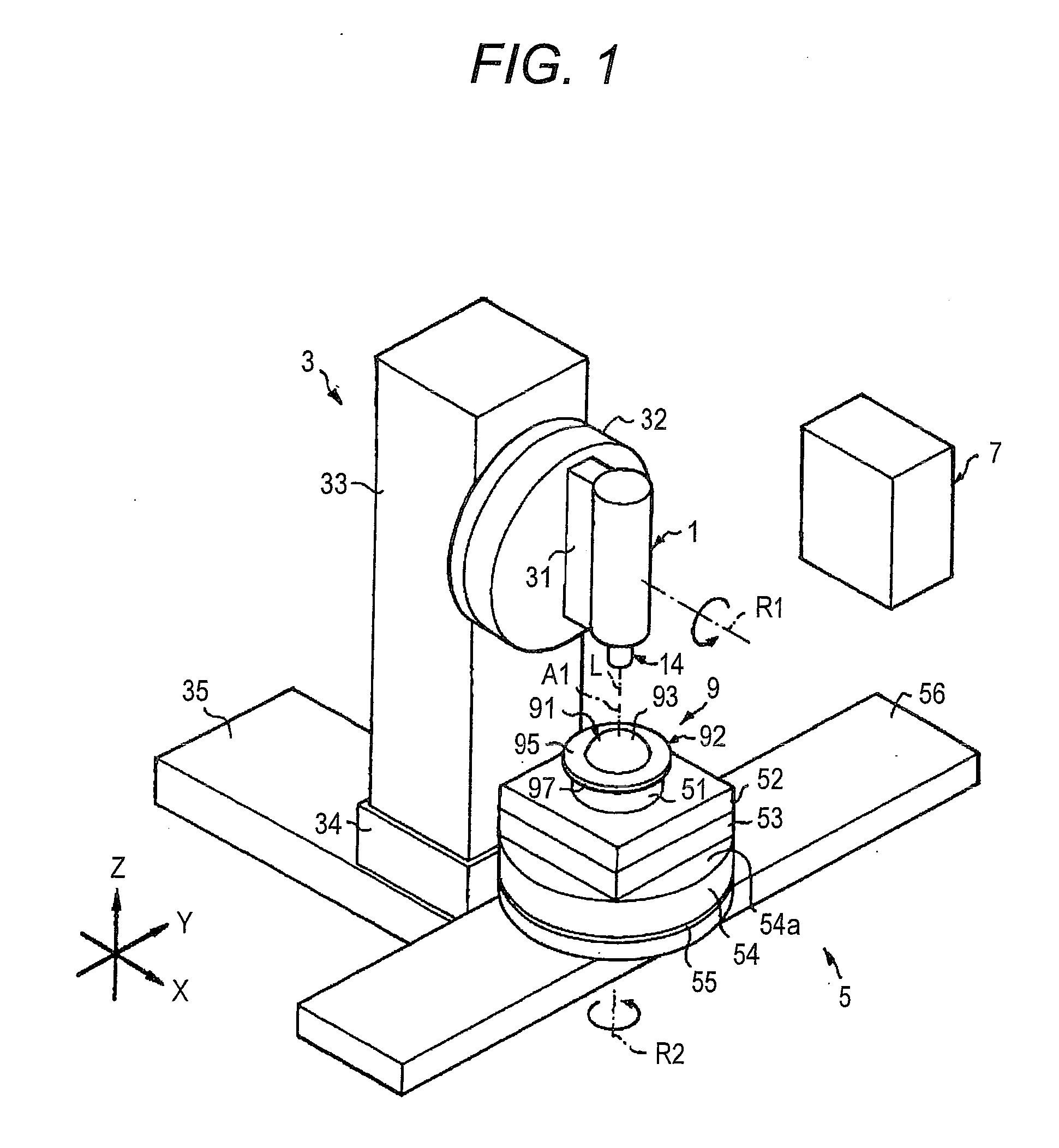
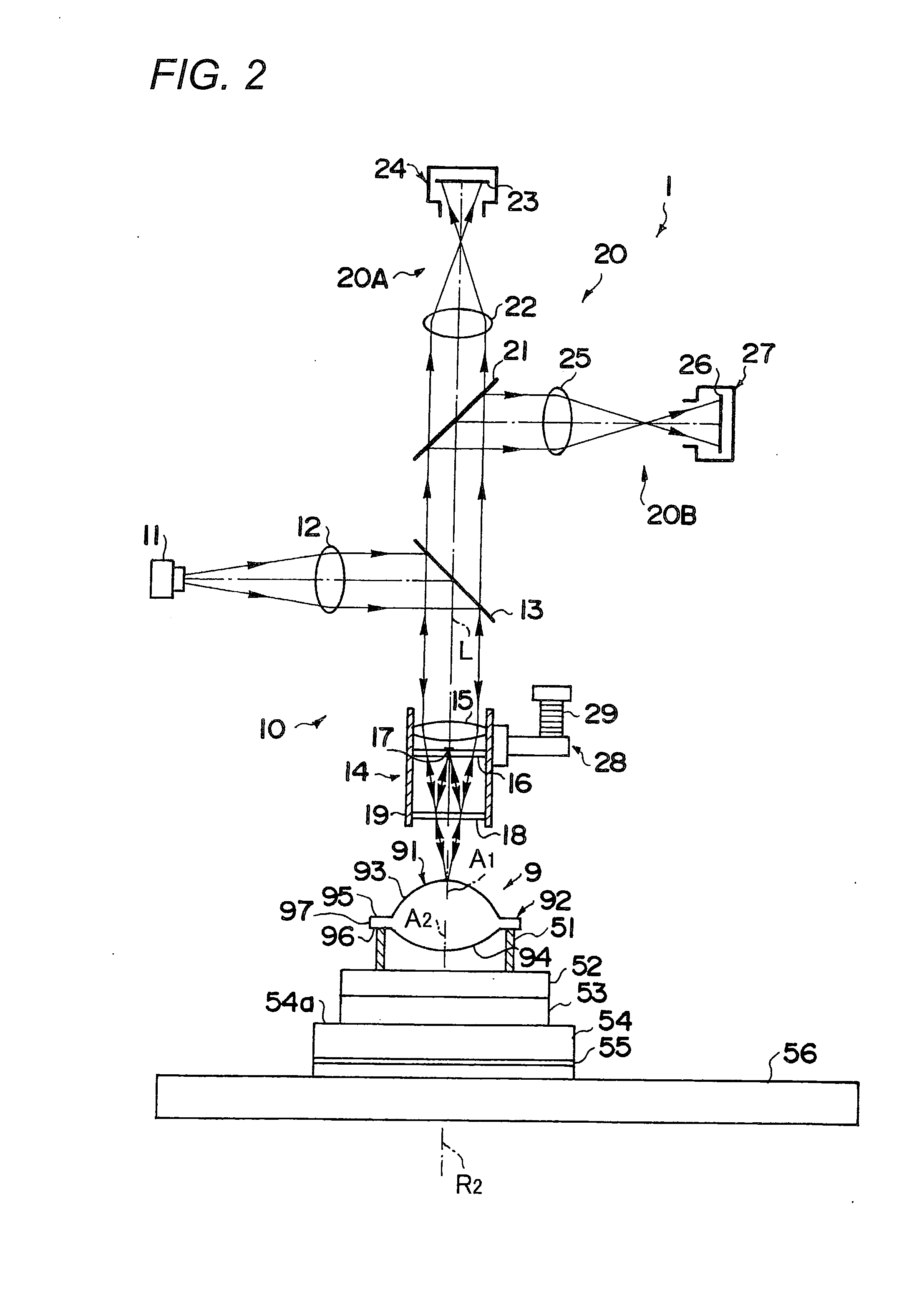
[0075]The configuration of a sample lens 9 as a sample and items to be measured in the first embodiment will be first described with reference to FIGS. 6 to 8.

[0076]As shown in FIGS. 6A and 6B, the sample lens 9 includes a lens portion 91 and a sharp flange portion 92 formed in the outer circumference of the lens portion 91. In design, the lens portion 91 includes a first curved surface 93 (which is aspheric) formed in a rotated surface shape centered on a first axis line A1 and a second curved surface 94 (which is spheric) formed in a rotated surface shape centered on a second axis line A2. The flange portion 92 includes a flange top surface 95 and a flange back surface 96 which are formed respectively in a ring shape and a flange side surface 97 formed in a cylindrical shape. In design, the first axis line A1 is an outer-diameter central axis of the first curved surface 93 and the second axis line A2 is an outer-diameter central axis of the second curved surface 94.

[0077]In the sa...

second embodiment

[0155]The configuration of a sample lens 109 as a sample and items to be measured according to a second embodiment of the invention will be described below with reference to FIGS. 19 and 20.

[0156]In design, as shown in FIG. 19, the sample lens 109 includes a sample top surface having a first curved surface 191 (which is aspheric) formed in a rotated surface shape centered on a first axis line A11, a sample back surface having a second curved surface 192 (which is spheric) formed in a rotated surface shape centered on a second axis line A12, and an edge surface 193 (the end surface of the sample lens 109) formed in a cylindrical surface shape.

[0157]In the second embodiment, the sample top surface and the sample back surface are defined as described above, but the top surface of the sample lens 109 shown in FIG. 19A may be defined as the sample back surface (in this case, the curved surface denoted by reference numeral 191 is called second curved surface and the axis line denoted by r...


PUM


Abstract

A process of measuring a shape while changing the relative posture of an microscopic interferometer to a sample lens which is rotated about a rotation axis is divided into a process of measuring a top surface in a state where the sample lens is supported from a back surface and a process of measuring a back surface in a state where the sample lens is supported from the top surface. By combining first shape information of a flange side surface acquired by the process of measuring the top surface and second shape information of the flange side surface acquired by the process of measuring the back surface, the relative positional relation between the sample top surface and the sample back surface is calculated.

Description

CROSS-REFERENCE TO RELATED APPLICATION[0001]This application is based on and claims priority under 35 USC 119 from Japanese Patent Application No. 2009-058778 filed on Mar. 11, 2009, Japanese Patent Application No. 2009-058779 filed on Mar. 11, 2009, and Japanese Patent Application No. 2009-212382 filed on Sep. 14, 2009.BACKGROUND[0002]1. Technical Field[0003]The present invention relates to a three-dimensional shape measuring method and a three-dimensional shape measuring device for measuring the shape of a sample such as an aspheric lens, and more particularly, to a three-dimensional shape measuring method and a three-dimensional shape measuring device which can be suitably used to acquire a variety of shape information on a sample, such as the position misalignment of central axes of top and back surfaces and the roundness of a sample side surface, in addition to the shapes of sample top and back surfaces.[0004]2. Related Art[0005]In a related art, a method of illuminating a top ...

Claims


Application Information

Patent Timeline
Patent Type & Authority Applications(United States)
IPC IPC(8): G01B11/25
CPCG01B11/2441G01M11/0271G01M11/025G01M11/0221
Inventor GE, ZONGTAOTOMIMIZU, MASAAKIKANDA, HIDEOSAITO, TAKAYUKIKOIZUMI, NOBORUMOCHITATE, SEIJITAKANO, SHIGEYUKIIWAZAKI, HIROYUKI
Owner FUJI PHOTO OPTICAL CO LTD
Why Eureka
Try Eureka