Surrounding conditions display apparatus

Inactive Publication Date: 2006-10-24
TOYOTA CENT RES & DEV LAB INC
View PDF9 Cites 35 Cited by
  • Summary
  • Abstract
  • Description
  • Claims
  • Application Information

AI Technical Summary

Benefits of technology

[0042]When the tenth feature is to be combined with the fourth feature, the following action and effect can be attained. When the brightness at the origin of the area is increased with the gradient of the brightness maintained constant, the entirety of the colored area becomes brighter, which is equivalent to the area being expanded. Further, the area can be narrowed by increasing the gradient of the brightness. Moreover, the area can be narrowed by increasing the brightness at the origin of the area and by increasing the gradient of the brightness. In other words, the area can be narrowed, rendered brighter, or caused to have a clear boundary by means of changing the manner of modulation with the distance from the origin of the area. This enables the driver to know, from the display condition of the area, that the movable body has approached closer to the obstacle, and to perform a more proper collision avoiding operation.
[0043]When the tenth feature is to be combined with the fifth feature, although a monochrome imag

Problems solved by technology

However, in actuality, accurately specifying an

Method used


Image

  • Surrounding conditions display apparatus
  • Surrounding conditions display apparatus
  • Surrounding conditions display apparatus

Examples


first embodiment

[0064]An apparatus according to a first embodiment is configured to capture the image of an area at the back of a vehicle (movable body) so as to display the back area image, and to display an area including an obstacle on the back area image to thereby provide an alert to a driver.

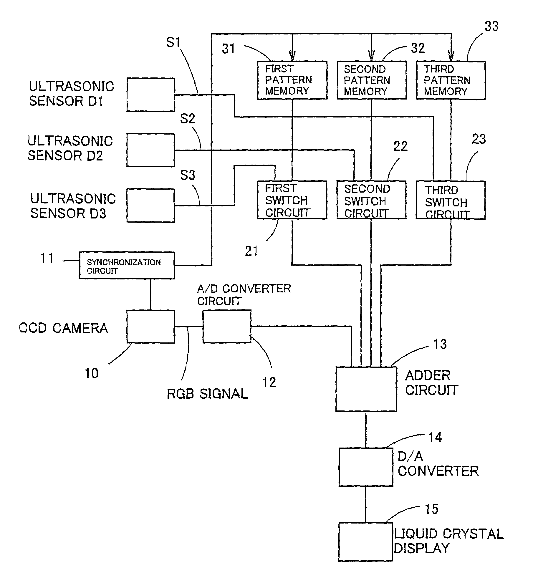
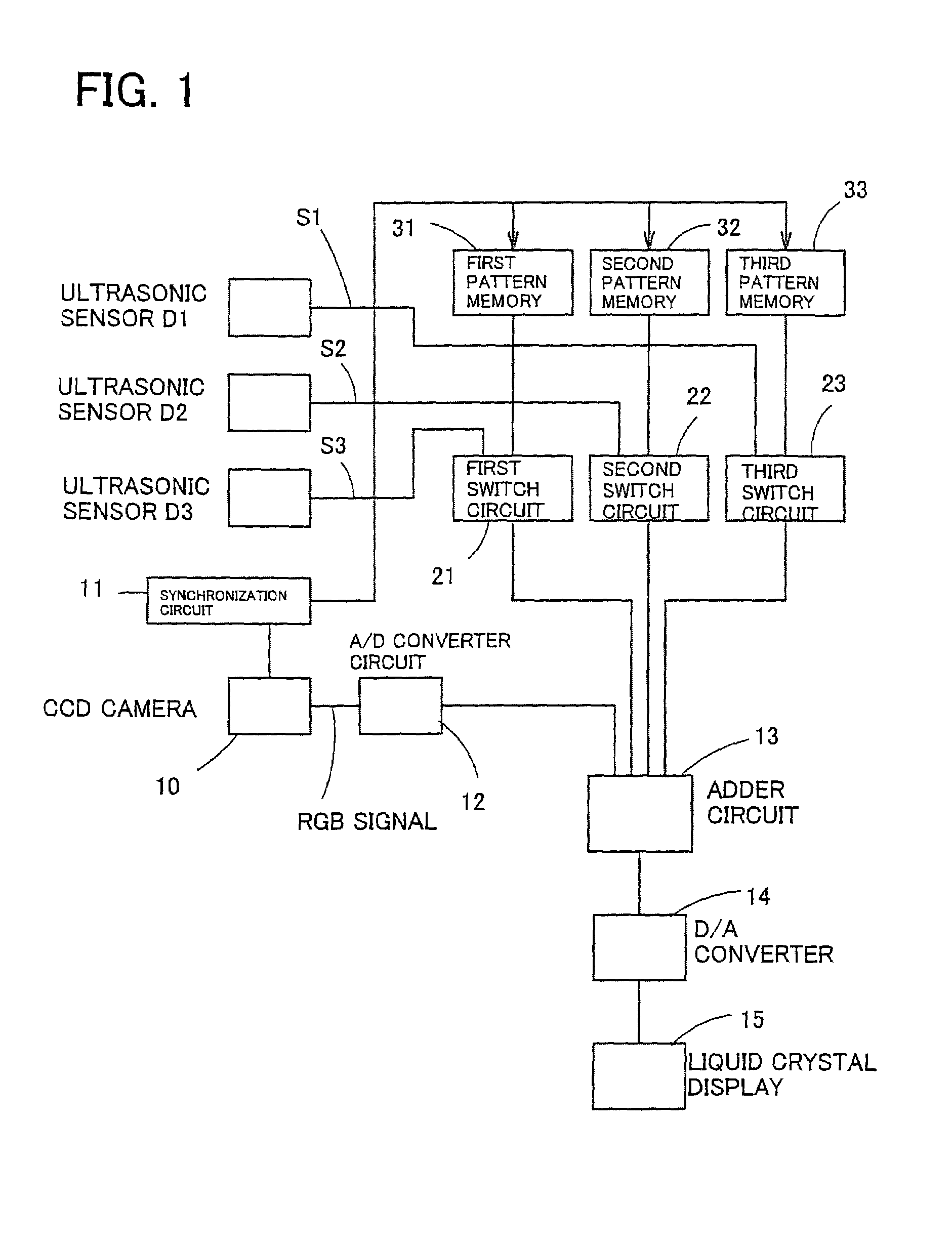
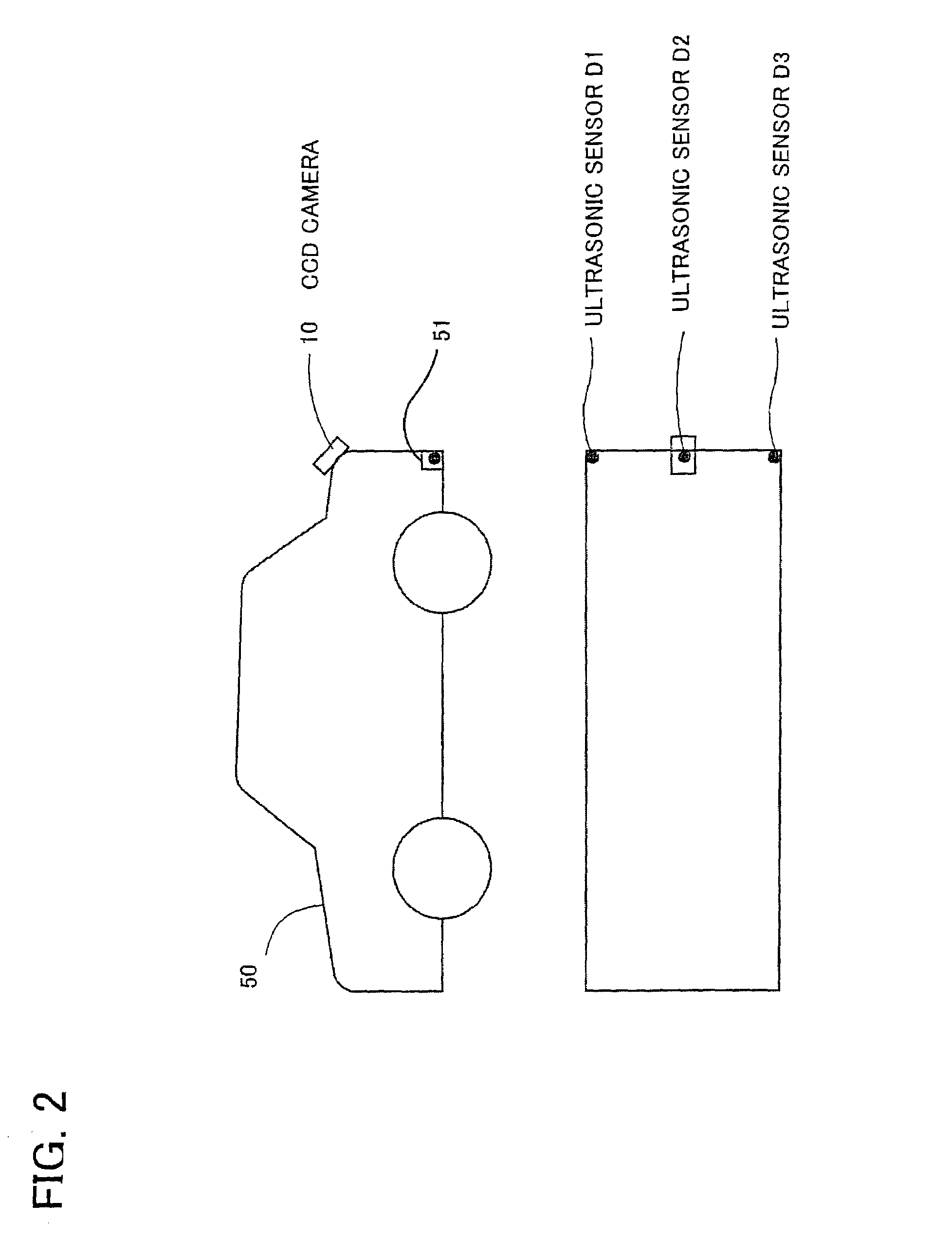
[0065]FIG. 1 is a block diagram showing the configuration of a surrounding conditions display apparatus according to the present embodiment. FIG. 2 is a side view of a vehicle showing the positions of a CCD camera (image capturing unit) and ultrasonic sensors (distance detection unit) used in the present apparatus.

[0066]In FIG. 2, a CCD camera 10 is disposed on the trunk lid of a vehicle 50 in an inclined condition such that the optical axis of the CCD camera 10 is directed to the road surface, whereby the CCD camera 10 can capture the image of a road surface area at the back of the vehicle. FIG. 5 shows an image of the back area captured by the CCD camera 10. In FIG. 5, reference numerals 61 to 65 denote...

second embodiment

[0080]A second embodiment will now be described with reference to FIG. 7.

[0081]An apparatus of the present embodiment is formed by a computer system. A distance-direction measurement unit 75 measures a distance to an obstacle and the direction to the obstacle on the basis of reflection of electromagnetic waves generated by, for example, a radar system or a laser radar system. The distance-direction measurement unit 75 outputs digital data representing the measured distance and direction. The digital data are supplied to a CPU 70 via an interface 78. A CCD controller 77 scans an imaged captured by a CCD camera 76 in order to obtain a RGB value for each pixel, which is then stored in first frame memory 71. On the basis of the image data of a single frame stored in the first frame memory 71, a DSP (digital signal processor) 73 outputs a display signal to a liquid crystal display 74, whereby the captured image is displayed in real time. The CPU 70 generates a modulation image to be supe...


PUM


Abstract

A surrounding conditions display apparatus captures an image of an area surrounding a movable body and displays the captured image. The apparatus includes a CCD camera for capturing an image of the surrounding are, ultrasonic sensors for detecting a distance to an obstacle present in the surrounding area, and a liquid crystal display for displaying the image captured by the image capturing unit. A color image representing an area including the obstacle is superposed on the displayed image in such a manner that the brightness of the color image decreases with increasing distance from the origin of the area.

Description

[0001]This is a patent application based on a Japanese patent application No. 2001-145616 which was filed on May 15, 2001 and which is incorporated herein by reference.BACKGROUND OF THE INVENTION[0002]1. Field of the Invention[0003]The present invention relates to an apparatus for displaying the conditions of the surroundings of a movable body, and more particularly to an apparatus for capturing and displaying an image of a surrounding area which, if an obstacle is present in the surrounding area, displays on the captured image an area in which the obstacle is present.[0004]2. Description of the Related Art[0005]Japanese Patent Application Laid-Open (kokai) Nos. 3-85069, 2-299944, and 2000-184368 disclose conventional apparatuses for displaying surrounding conditions of a vehicle, which is a movable body. The apparatus of Japanese Patent Application Laid-Open No. 3-85069 displays a distance to an obstacle on a screen which displays an image of an area at the back of a vehicle (herei...

Claims


Application Information

Patent Timeline
IPC IPC(8): B60Q1/00B60R21/00B60R1/00G01S13/93G01S15/87G06T1/00H04N7/18
CPCB60R1/00B60R2300/301B60R2300/307B60R2300/8093
Inventor YAMADA, KEIICHI
Owner TOYOTA CENT RES & DEV LAB INC
Why Eureka
Try Eureka