Rear projection screen

a projection screen and rear projection technology, applied in the field of rear projection screens, can solve the problems of lowering the contrast of image light, degrading the shape accuracy of the black matrix, etc., and achieve the effects of improving the transmission factor of image light, reducing the stray light during exposure, and improving the accuracy of the opening rate of the single lens

Inactive Publication Date: 2006-06-15
ARISAWA MFG CO LTD
View PDF0 Cites 17 Cited by
  • Summary
  • Abstract
  • Description
  • Claims
  • Application Information

AI Technical Summary

Benefits of technology

[0011] In the lens array described above, the plurality of single lenses are arrayed without leaving space among them and the incident-side black matrix is formed with a uniform width when seen from the direction of the optical axis of the single lens in the lens boundaries. It narrows down an area of the lens boundaries, thus improving transmission factor of image light.
[0012] In the rear projection screen described above, the lens boundary may have side walls parallel to the optical axis of the single lens and a bottom face vertical to the side walls, and the incident-side black matrix may be formed by depositing it in an inner part surrounded by the bottom face and side walls. Thereby, even if a thickness of the incident-side black matrix varies within a range of height of the side walls in the direction of the optical axis, the width of the incident-side black matrix seen from the optical axis direction does not change. Accordingly, it brings about effects that accuracy of rate of opening of the single lens seen from the light source side increases and that light transmissivity of the fly-eye lens varies less.
[0013] According to a second aspect of the invention, there is provided a rear projection screen for transmitting image light, having a Fresnel lens for collimating the image light and a lens array for diffusing the collimated image light in order from a light source of the image light to a viewer side, wherein the lens array has a plurality of single lenses arrayed evenly on an incident plane for inputting the collimated image light and having each focal point in the vicinity of outgoing plane of the lens array, an incident-side black matrix, formed in lens boundaries where the plurality of single lenses adjoin each other, for blocking the image light incident on the lens boundaries and an outgoing-side black matrix through which an opening centering on an optical axis of the single lens is formed in the vicinity of each focal point of the plurality of single lenses in the vicinity of the outgoing plane of the lens array. It brings about the same effect with the first aspect of the invention.
[0014] According to a third aspect of the invention, there is provided a method for manufacturing a rear projection screen having a plurality of single lenses, having steps of molding the plurality of single lenses on one plane of a transparent substrate so as to have focal points in the vicinity of the other plane of the transparent substrate, forming an incident-side black matrix for blocking light from entering the lens boundaries by filling light-blocking ink in the lens boundaries where the plurality of single lenses adjoin each other, forming uncured UV curable resin on a plane of the transparent substrate on the side opposite from the single lens, exposing UV to cure the UV curable resin located in the vicinity of each focal point of the single lenses by inputting the UV almost parallel to the optical axis of the single lens from a lens plane of the single lens, and forming a pattern of outgoing-side black matrix in an uncured part of the UV curable resin. Such manufacturing method allows the adhesive in the optical axis part to be exposed at high contrast because the incident-side black matrix prevents UV from entering the lens boundaries, thus reducing stray light during exposure. It also allows the contrast between the light transmitting part (openings) of the outgoing-side black matrix and the light-blocking part to be enhanced. Still more, because the incident-side black matrix blocks UV from entering the lens boundaries, a diameter of the UV ray exposing the adhesive becomes narrow, allowing the size of opening of the outgoing-side black matrix to be contracted. It then allows the aperture ratio of the outgoing-side black matrix to be lowered, thus reducing reflectance of external light. The rear projection screen capable of outputting the image light having high contrast may be produced by the effects described above.
[0015] The method for manufacturing the rear projection screen described above may further include a step of controlling wettability of the lens array and the light-blocking ink so that a range of the incident-side black matrix seen from the direction of the optical axis of the single lens falls within a predetermined range. It allows the range of the incident-side black matrix to be readily controlled.
[0016] According to a fourth aspect of the invention, there is provided a method for manufacturing a rear projection screen having a plurality of single lenses, having steps of applying light-blocking agent to part of a mold for molding lens boundaries where the plurality of single lenses adjoin each other in the mold for molding the plurality of single lenses, forming the plurality of single lenses on one plane of a transparent substrate by using the mold on which the light-blocking agent has been applied and forming an incident-side black matrix for blocking light incident on the lens boundaries by transferring the light-blocking agent to the lens boundaries, forming uncured UV curable resin on the other plane of the transparent substrate on the side opposite from the single lens, exposing UV to cure the UV curable resin located in the vicinity of each focal point of the plurality of single lenses by inputting the UV almost parallel to the optical axis of the single lens from a lens plane of the single lens and forming a pattern of outgoing-side black matrix in uncured part of the UV curable resin. It brings about the same effect with the third aspect of the invention. Still more, because the incident-side black matrix is formed by transferring the light-blocking agent from the mold to the lens boundary, the range of the incident-side black matrix may be accurately controlled. The rear projection screen capable of outputting the image light having high contrast may be produced by the effects described above.

Problems solved by technology

However, the conventional rear projection screen has had a problem that the image light incident on a boundary part of the single lenses is not condensed to the focal point of the single lens and becomes stray light, thus lowering the contrast of the image light.
Still more, there has been a problem in producing the lens array that UV incident on the boundary part of the single lenses degrades its contrast in exposing the UV curable resin around the focal point, thus degrading the accuracy of shape of the black matrix as a result.

Method used


Image

  • Rear projection screen
  • Rear projection screen
  • Rear projection screen

Examples


Embodiment Construction

[0027] The invention will now be described based on preferred embodiments while showing operations of the invention based on the drawings, which do not intend to limit the scope of the invention, but exemplify the invention. All of the features and the combinations thereof described in the embodiments are not necessarily essential to the invention.

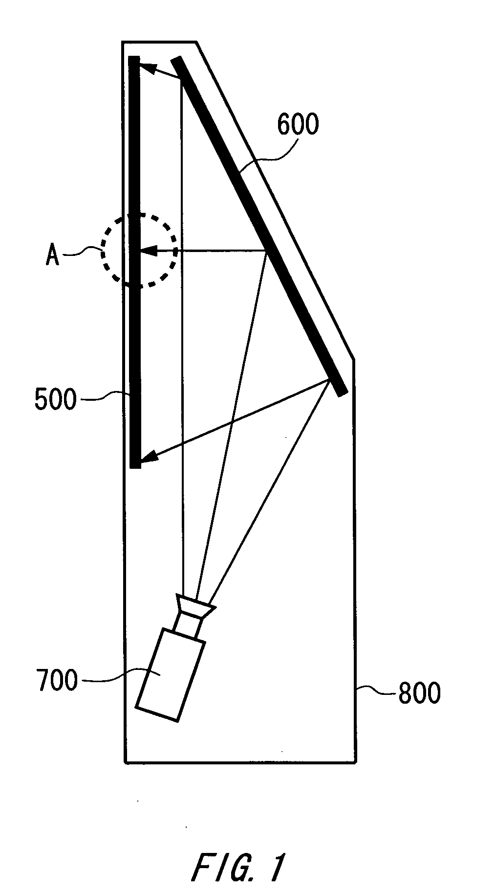
[0028]FIG. 1 shows a structure of a rear projection display 800 according to one embodiment of the invention. The rear projection display 800 has an optical engine 700, a mirror 600 and a screen 500. An image light outputted from the optical engine 700 is reflected by the mirror 600 and is inputted to the screen 500. The screen 500 realizes an adequate view angle by diffusing the incident image light and outputting it to a viewer side. The screen 500 is one example of the rear projection screen of the present invention.

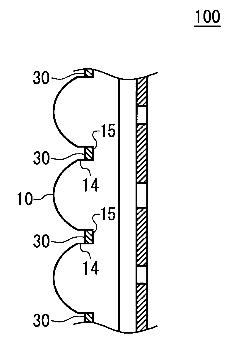
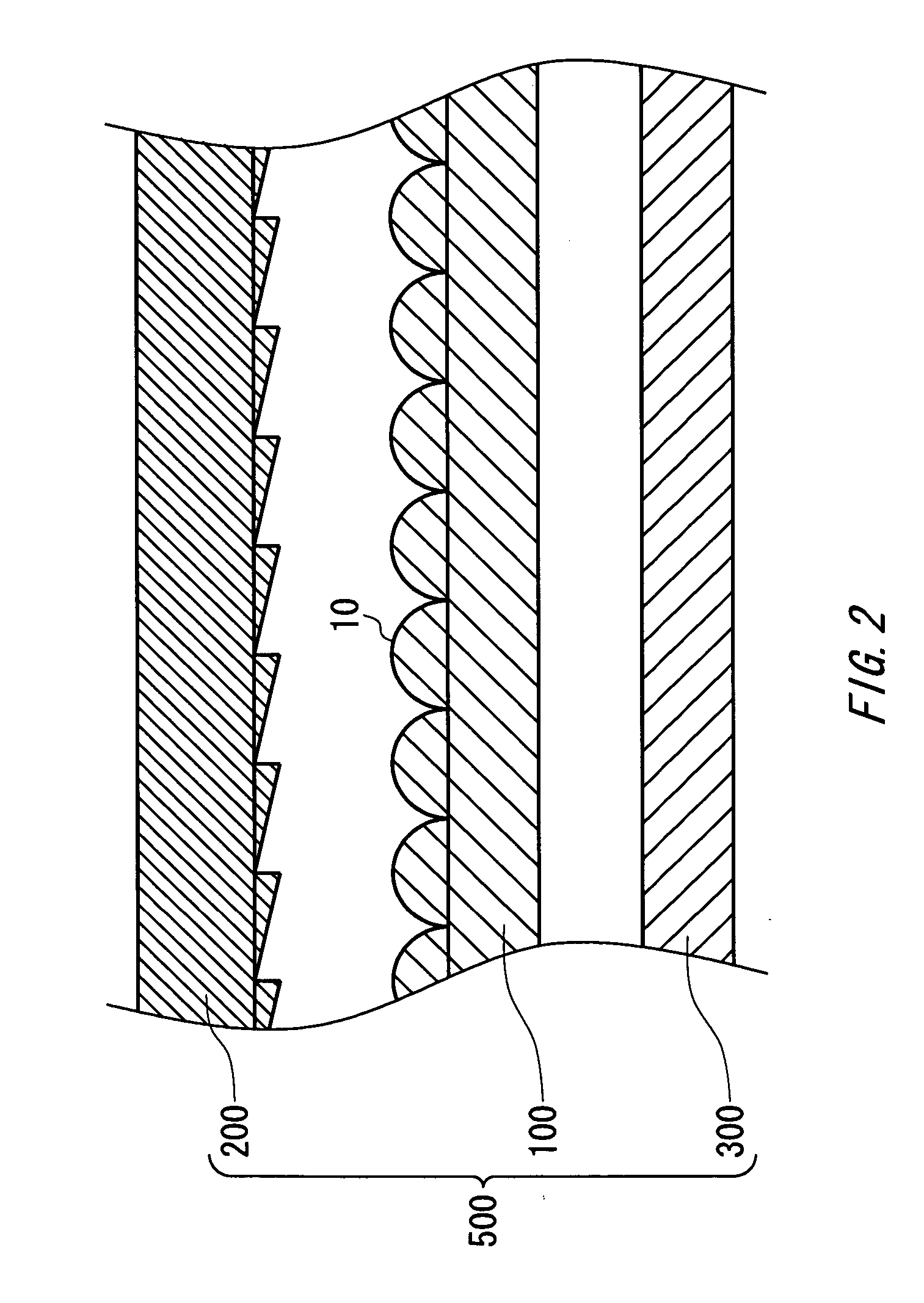
[0029]FIG. 2 shows a detailed structure of a part A in the screen 500 in FIG. 1. The screen 500 has a Fresnel lens 200, ...


PUM


Abstract

There is provided a rear projection screen for transmitting image light. The rear projection screen has a plurality of single lenses arrayed evenly on an incident plane for inputting the image light and having focal points in the vicinity of an outgoing plane of the rear projection screen, an incident-side black matrix, formed in lens boundaries where the plurality of single lenses adjoin each other, for blocking the image light incident on the lens boundaries and an outgoing-side black matrix in which an opening centering on an optical axis of the single lens is formed in the vicinity of each focal point of the plurality of single lenses in the vicinity of the outgoing plane of the rear projection screen.

Description

CROSS REFERENCE TO RELATED APPLICATION [0001] The present application claims priority from a Japanese Patent Application No. JP 2004-358244 filed on Dec. 10, 2004, the contents of which are incorporated herein by reference. BACKGROUND OF THE INVENTION [0002] 1. Field of the Invention [0003] The present invention relates to a rear projection screen and to a manufacturing method of the rear projection screen. [0004] 2. Background Art [0005] Conventionally, a lens array for diffusing image light is used as a rear projection screen that transmits the image light. The lens array has a plurality of single lenses on an image light incident side and a light-blocking layer (hereinafter referred to as a black matrix) through which a plurality of openings is formed centering on a focal point of each single lens on a viewer side. The black matrix provided on the viewer side causes the image light condensed by the single lenses to go out of the openings and absorbs most of outside light coming f...

Claims


Application Information

Patent Timeline
Patent Type & Authority Applications(United States)
IPC IPC(8): G03B21/60G03B21/62
CPCG03B21/625
Inventor YAKUSHIJI, KENICHISOYAMA, MAKOTOSHIMOTSUMA, HIROYUKIADACHI, KEISUKE
Owner ARISAWA MFG CO LTD
Why Eureka
Try Eureka