Rear projector

a projector and rear-facing technology, applied in the field of rear-facing projectors, can solve the problems of generating dispersion, affecting determining the limit of the display position of images,

Inactive Publication Date: 2004-02-05
SEIKO EPSON CORP
View PDF9 Cites 16 Cited by
  • Summary
  • Abstract
  • Description
  • Claims
  • Application Information

AI Technical Summary

Problems solved by technology

However, when such simple position adjuster where the position of the projection lens is horizontally or vertically adjusted is used for adjusting the position of the image, there is certain limit capable of adjusting the display position of the image and undisplayable area for displaying the image is formed on the screen even after adjusting the position of the projection lens.
Further, there is difference in the tolerance of the profile of the casing of the rear projector and the tolerance of the component installed in the casing, the tolerance causing difference in aspect ratio of the displayed image, so th...

Method used


Image

  • Rear projector
  • Rear projector
  • Rear projector

Examples


first embodiment

[0074] [First Embodiment]

[0075] A first embodiment of the present invention will be described below with reference to attached drawings.

[0076] [1-1. Primary Arrangement of Rear Projector]

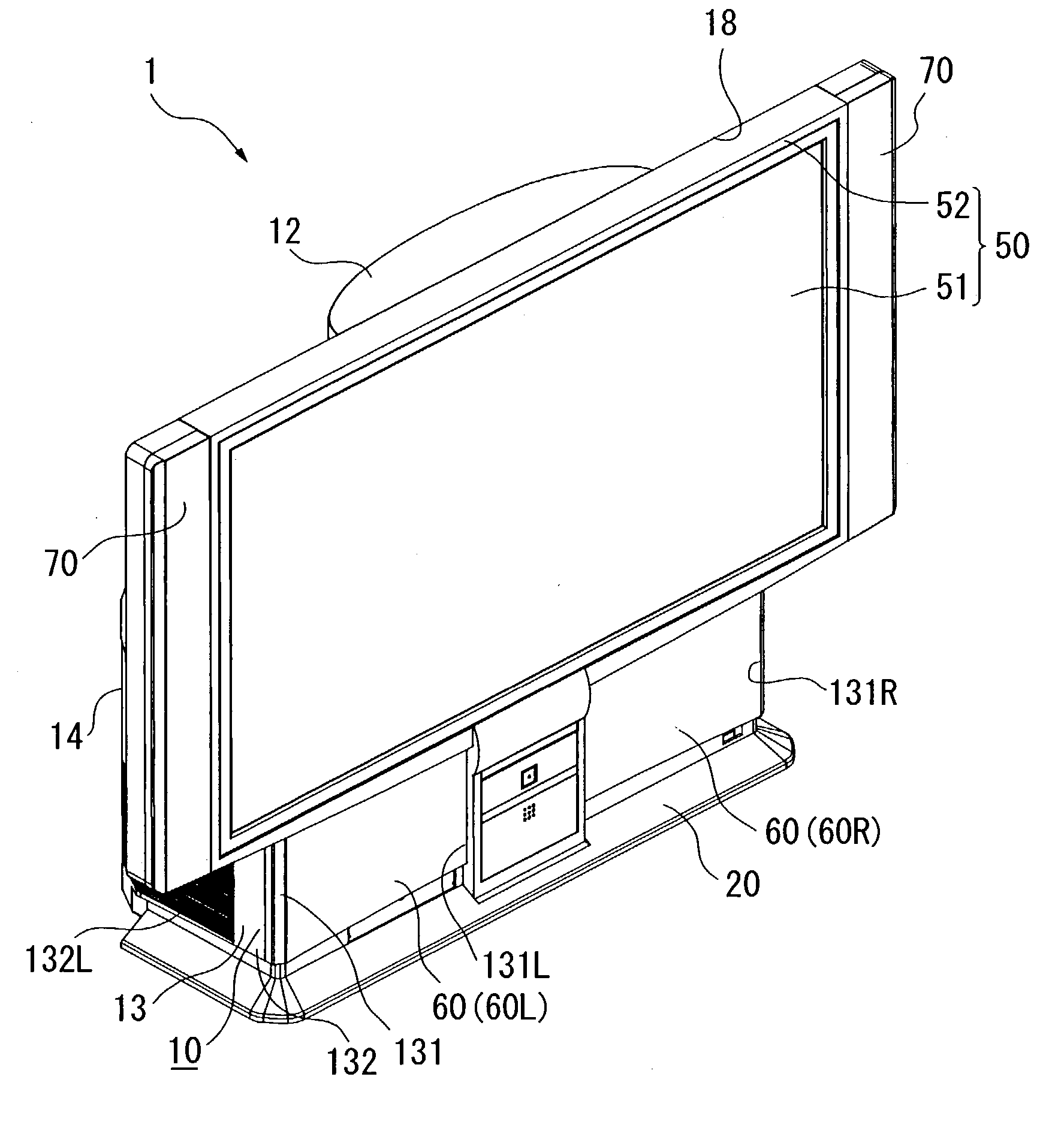
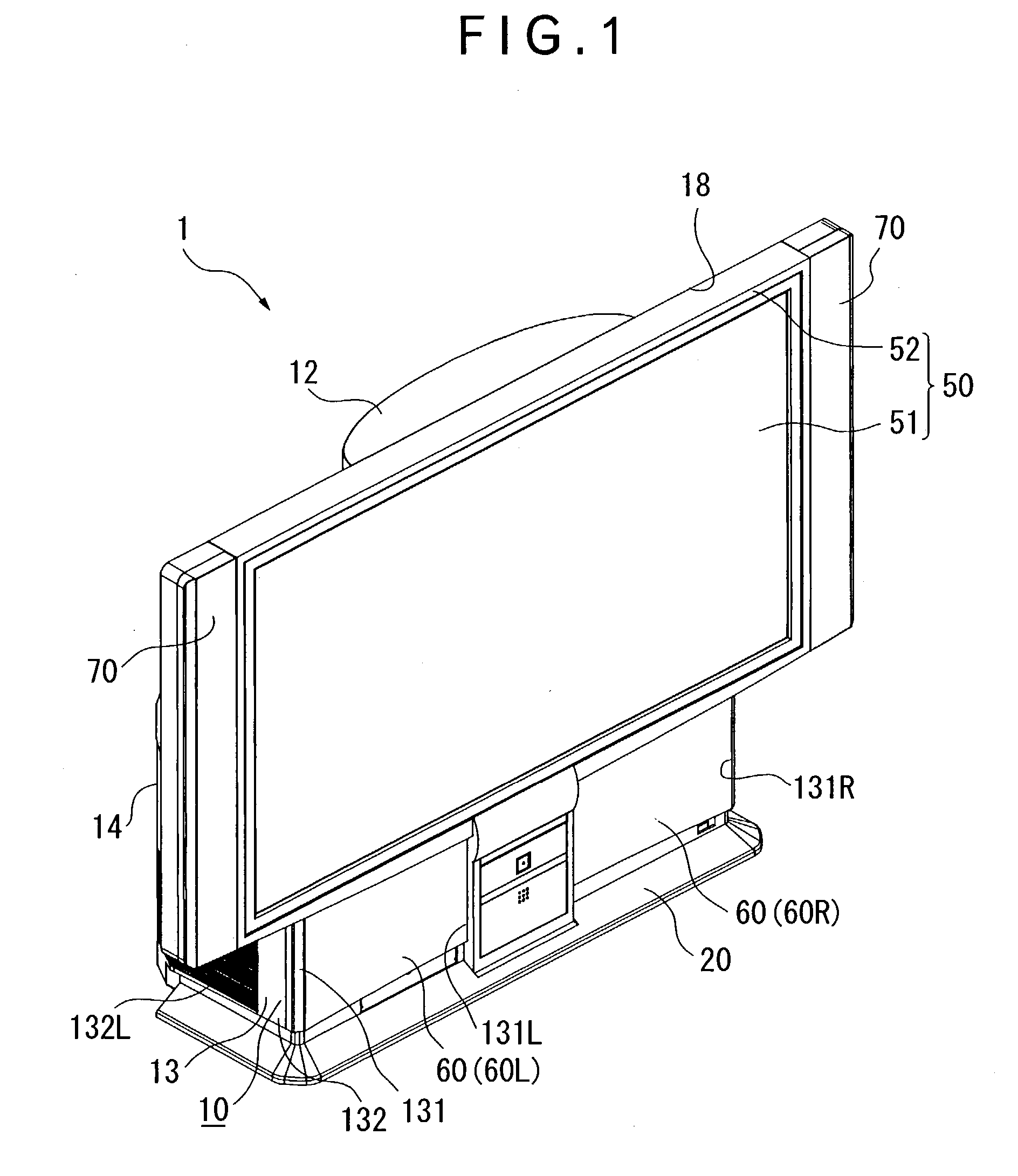
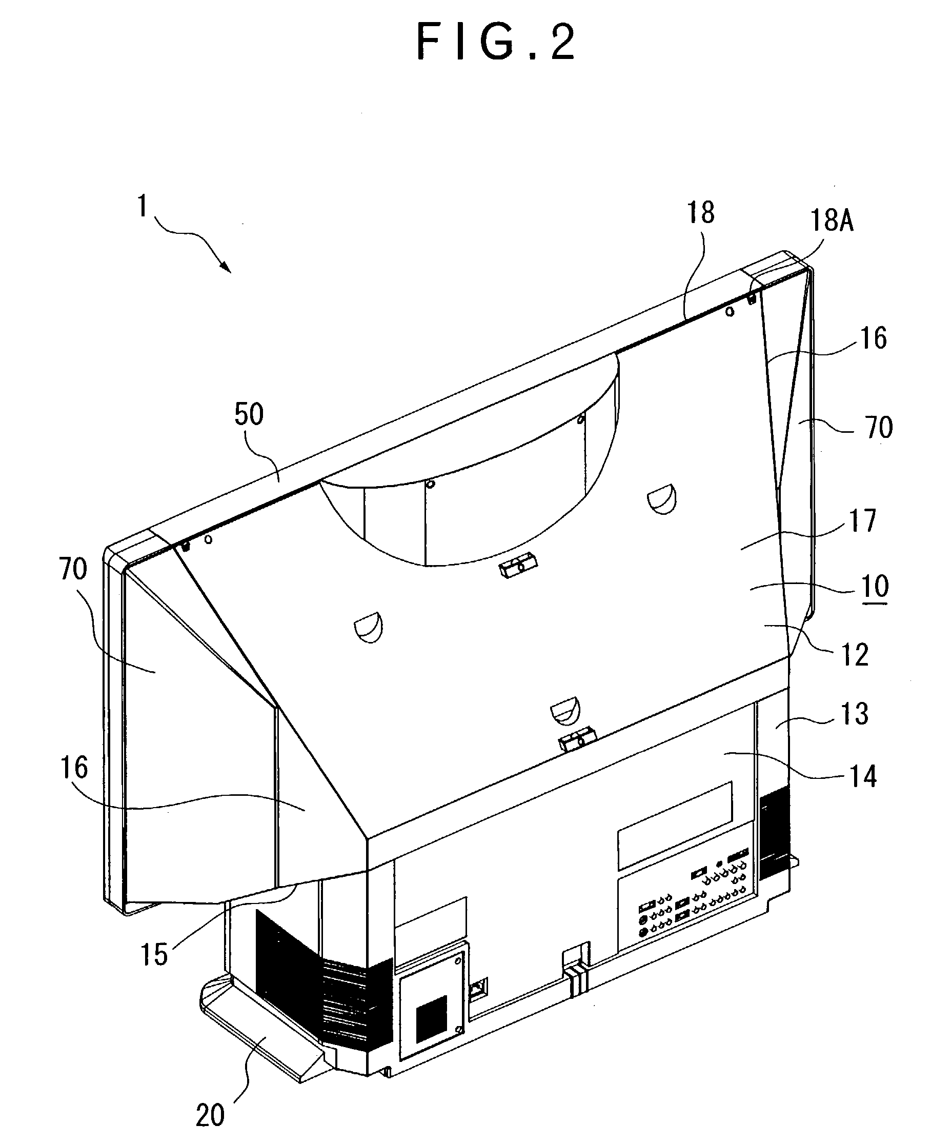
[0077] FIG. 1 is a perspective view showing a rear projector seen from front side according to an aspect of the present invention. FIG. 2 is a perspective view of the rear projector 1 seen from rear side. FIG. 3 is an exploded perspective view of the rear projector 1 seen from rear side, which specifically shows that a back cover 14 is removed from FIG. 2. FIG. 4 is an exploded perspective view of the rear projector 1 seen from bottom side. FIG. 5 is a vertical cross section showing the rear projector 1.

[0078] Primary arrangement of the rear projector 1 will be described below with reference to FIGS. 1 to 5.

[0079] As shown in FIGS. 1 to 5, the rear projector 1 modulates a light beam irradiated by a light source in accordance with image information to form an optical image and enlarges and projects t...

second embodiment

[0276] [Second Embodiment]

[0277] Next, second embodiment of the present invention will be described below.

[0278] In the following description, the same reference numeral will be attached to the same structure or the same component as in the first embodiment to omit or simplify detailed explanation thereof.

[0279] In the first embodiment, the base member 201 is provided in the cabinet 10 and is in contact with the receiver surface 21 of the leg 20. The support member 200 is disposed on the base member 201 and the optical unit body 401A is supported by the support member 200.

[0280] On the other hand, the base member 201 is spaced apart from the receiver surface 21 of the leg 20 in the cabinet 10 in the second embodiment. The support member 200 is disposed on the lower side of the base member 201 and the optical unit body 401A is supported by the support member 200.

[0281] [2-1. Attitude Adjusting Mechanism of Optical Unit Body]

[0282] FIG. 20 is an illustration schematically showing posi...


PUM


Abstract

In order to provide a rear projector capable of facilitating position adjustment of an image displayed on a screen and optimizing dispersion of the aspect ratio of the projected image caused by tolerance of components by adjusting the position of the image, a support member (200) is provided with a lateral position adjuster (202) as a planar position adjusting mechanism attached on a support plate of an interior unit in an opposing manner, an inclination adjuster (203) as an inclination position adjusting mechanism vertically provided on the lateral position adjuster (202), and a rotary position adjuster (204) as a rotary position adjusting mechanism attached to the inclination adjuster (203) slanted downward toward rear side.

Description

[0001] 1. Field of the Invention[0002] The present invention relates to a rear projector that displays image on a transmissive screen.[0003] 2. Description of Related Art[0004] Conventionally, a rear projector that displays a projected and enlarged image on a screen is known as a large-screen display device.[0005] In such rear projector, the light beam from a light source is irradiated on a transmissive liquid crystal panel, where the light beam is modulated in accordance with image information by the transmissive liquid crystal panel, and is enlarged by a projection lens, of which optical path is changed by a reflection mirror to be introduced to a rear side of a screen.[0006] According to the above arrangement, all of the components can be housed in a movable casing and the image on the screen can be viewed in a well-lighted room.[0007] In order to adjust the position of the image displayed on the screen, a position adjuster, which normally adjusts the position of the projection l...

Claims


Application Information

Patent Timeline
IPC IPC(8): G03B21/00G03B21/14G03B21/10G03B21/22G03B21/54H04N5/64H04N5/74
CPCG03B21/22G03B21/145G03B21/62G03B21/10H04N5/74
Inventor YAMADA, HARUYOSHIARAI, JUN
Owner SEIKO EPSON CORP
Why Eureka
Try Eureka