Stage apparatus and camera shake correction apparatus using stage apparatus

a technology which is applied in the field of stage apparatus and camera shake correction apparatus using stage apparatus, can solve the problems of difficult to make all of the y-direction rod portion, complicated structure of stage apparatus disclosed in japanese laid-open patent publication h8-304868, and deterioration of stage apparatus operating characteristics

Inactive Publication Date: 2006-01-12
RICOH IMAGING COMPANY
View PDF4 Cites 39 Cited by
  • Summary
  • Abstract
  • Description
  • Claims
  • Application Information

AI Technical Summary

Benefits of technology

[0012] The present invention provides a stage apparatus having a structure enabling the Y-direction rod portion and the pair of X-direction rod portions of either the Y-direction movable member or the X-direction movable member to be positioned so as to lie in one plane in an easy manner, and also provides a camera sake correction apparatus using such a stage apparatus.

Problems solved by technology

However, the structure of the stage apparatus disclosed in Japanese laid-open patent publications H8-304868 is complicated because the stage apparatus needs to be provided with positioning members which support front and rear surfaces of the movable stage at three points in addition to the stationary support plate, the Y-direction movable member and the movable stage (X-direction movable member).
In this stage apparatus, if all the Y-direction rod portion and the pair of X-direction rod portions of the Y-direction movable member do not lie in one plane, the Y-direction movable member cannot move smoothly relative to the stationary support plate while the movable stage (X-direction movable member) cannot move in the X-direction smoothly relative to the Y-direction movable member either, which deteriorates the operating characteristics of the stage apparatus.
Nevertheless, it is generally the case that the Y-direction movable member is molded as a single member, and it is not easy for the Y-direction movable member to be molded so that all of the Y-direction rod portion and the pair of X-direction rod portions of the Y-direction movable member lie in one plane with a high degree of precision.
Moreover, it is difficult to make all of the Y-direction rod portion and the pair of X-direction rod portions of the Y-direction movable member lie in one plane after the completion of molding of the Y-direction movable member by adjusting the angle between the axis of the Y-direction rod portion and the axis of each X-direction rod portion.

Method used


Image

  • Stage apparatus and camera shake correction apparatus using stage apparatus
  • Stage apparatus and camera shake correction apparatus using stage apparatus
  • Stage apparatus and camera shake correction apparatus using stage apparatus

Examples


first embodiment

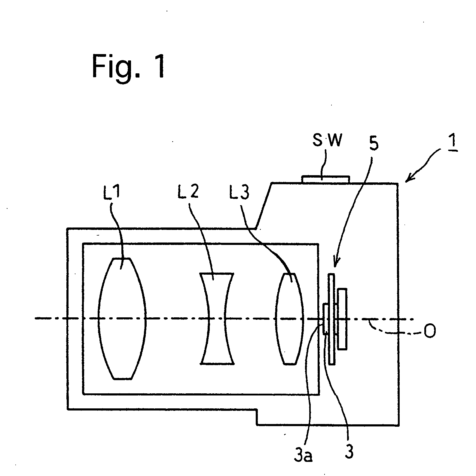
[0058] a camera shake correction apparatus (image stabilizer) according to the present invention will be hereinafter discussed with reference to FIGS. 1 through 15. The camera shake correction apparatus 5 is incorporated in a digital camera 1 as shown in FIG. 1.

[0059] As shown in FIG. 1, the digital camera 1 is provided therein with a photographing optical system including a plurality of lenses L1, L2 and L3. A CCD image sensor (image pickup device) 3 is provided behind the lens L3. The CCD image sensor 3 is provided with an image pickup surface 3a which is perpendicular to an optical axis O of the photographing optical system and is located on an image plane of the photographing optical system. The CCD image sensor 3 is secured to the camera shake correction apparatus 5 that is incorporated in the digital camera 1.

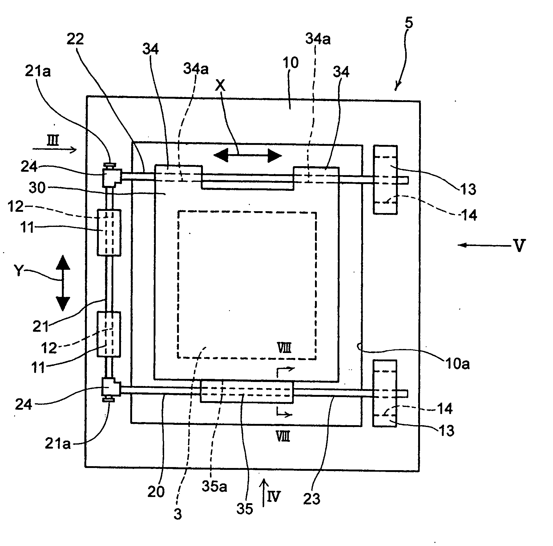
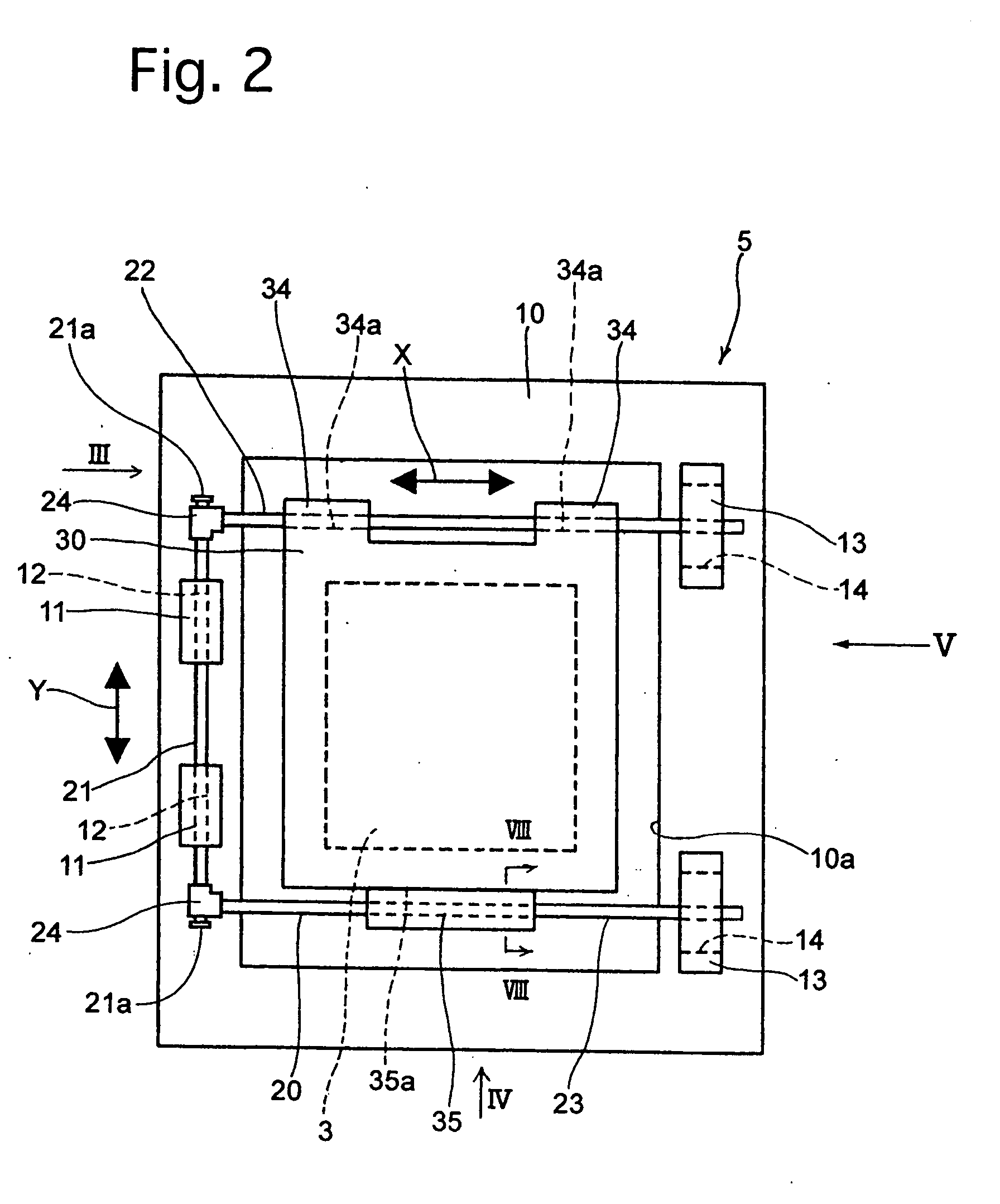
[0060] The camera shake correction apparatus 5 is constructed as described in the following description with reference to FIGS. 2 through 15.

[0061] As shown in FIGS. 2,...

second embodiment

[0099] The characteristic structure of the camera shake correction apparatus will be discussed hereinafter.

[0100] A stationary support plate 110, which corresponds to the stationary support plate 10, is provided, on a rear surface of the stationary support plate 110 in the vicinity of the upper end thereof, with a pair of X-direction guide portions 16 which project rearward to be laterally spaced from each other. The pair of X-direction guide portions 16 are provided with a pair of X-direction guide holes 16a, respectively, which are formed as through-holes extending in the X-direction to be aligned in the X-direction. The stationary support plate 110 is provided, on a rear surface thereof in the vicinity of the lower end of the stationary support plate 110, with a pair of X-direction support portions 17 which project rearward to be laterally spaced from each other, and the pair of X-direction support portions 17 are provided with a pair of Y-direction elongated holes 17a, respectiv...


PUM


Abstract

A stage apparatus includes a stationary support plate; a Y-direction movable member supported on, and parallel to, the stationary support plate so as to be relatively movable in a Y-direction, the Y-direction movable member including a Y-direction rod portion and a pair of X-direction rod portions, wherein the Y-direction rod portion extends in the Y-direction, and the pair of X-direction rod portions are joined to the Y-direction rod portion to extend in an X-direction both parallel to the stationary support plate and perpendicular to the Y-direction; and an X-direction movable member supported by the pair of X-direction rod portions to be movable in the X-direction relative to the Y-direction movable member. At least one of the pair of X-direction rod portions is rotatable about an axis of the Y-direction rod portion relative to the Y-direction rod portion.

Description

BACKGROUND OF THE INVENTION [0001] 1. Field of the Invention [0002] The present invention relates to a stage apparatus which moves a movable stage in two orthogonal directions in a plane, and a camera shake correction apparatus using the stage apparatus. [0003] 2. Description of the Prior Art [0004] A known stage apparatus used as a camera shake correction apparatus in which a movable stage is moved in two orthogonal directions in a plane is described in, for example, Japanese laid-open patent publications H8-304868 and H8-152659. [0005] Such a known stage apparatus (shake correction apparatus) has a structure which will be discussed hereinafter. Namely, a Y-direction guide member which projects from one of opposite surfaces of a stationary support plate (stationary support base-plate) is provided with a Y-direction linear slot which is elongated in a specific direction (Y-direction), and one of the two rod portions of a Y-direction movable rod (Y-direction movable member), which ar...

Claims


Application Information

Patent Timeline
Patent Type & Authority Applications(United States)
IPC IPC(8): H04N5/225
CPCH04N5/2253H04N5/23287H04N5/23248H04N23/54H04N23/68H04N23/687G03B5/00
Inventor SEO, SHUZO
Owner RICOH IMAGING COMPANY
Why Eureka
Try Eureka