
Variable reflectance mirrors and windows

a mirror and variable reflectance technology, applied in mirrors, instruments, vehicle components, etc., can solve the problems of reducing the reflective viewing area of the mirror assembly, blocking more of the driver's view through the windshield, and window also providing further problems

Active Publication Date: 2006-01-12
GENTEX CORP
View PDF3 Cites 194 Cited by
  • Summary
  • Abstract
  • Description
  • Claims
  • Application Information

AI Technical Summary

Benefits of technology

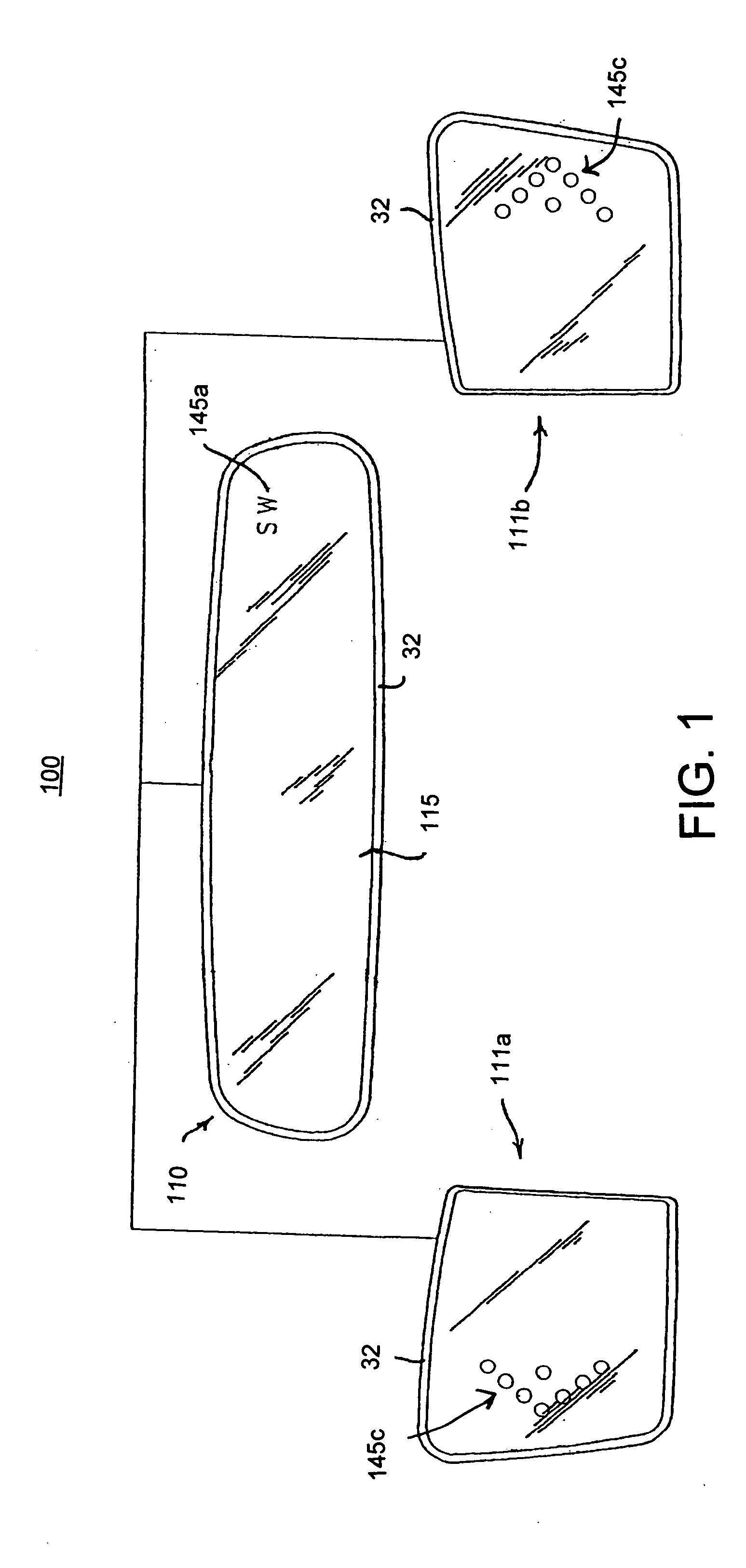
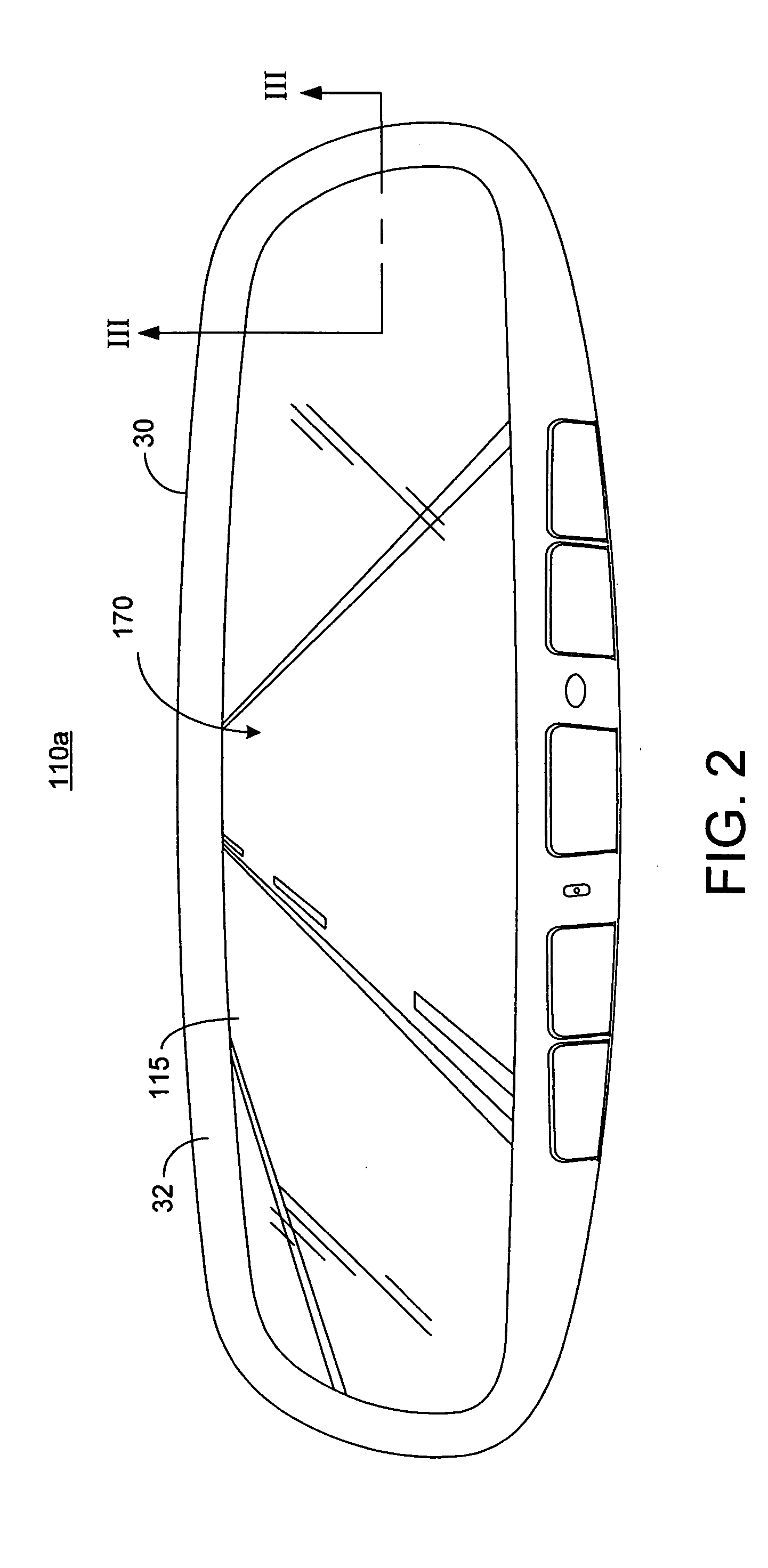
[0014] According to another aspect of the present invention, a rearview mirror assembly is provided for a vehicle comprising: a housing adapted for attachment to the vehicle; a mirror element positioned within the housing; and a display moveably mounted to the housing, the display movable between a first position where the display may be viewed by a vehicle occupant, and a second position where the display may not be readily viewed by a vehicle occupant.

Problems solved by technology

There are several issues with designing a rearview mirror assembly incorporating such an electronic device, particularly when the rearview mirror assembly is an inside mirror assembly.
If the electronic device is disposed adjacent the mirror element, it causes the inside rearview mirror assembly to have a larger area, which disadvantageously blocks more of the driver's view through the windshield.
This solution, however, reduces the reflective viewing area of the mirror assembly.
Such a window also provides further problems when the reflective layer serves as an electrode for an electro-optic mirror element, such as an electrochromic mirror element.
Thus, the window acts to eliminate the electrode across a portion of the electrochromic mirror element thereby causing an objectionable non-uniform coloration of the mirror element when dimmed.
Although such a transflective layer is very effective for most forms of electronic devices, the transflective layer tends to block a large percentage of light (passing about 10% of incident light).
As a result, the light from a display or light source behind the mirror element is not efficiently transmitted through the transflective layer.
This becomes more problematic when a display is provided that displays images of variable brightness during periods of bright daylight.
This is because the reflectivity of the transflective layer is still rather high, and therefore, there is large light loss going through transflective layer producing poorer contrast.
Again, this is disadvantageous in that the video display blocks the driver's view to the front of the vehicle.
Further, the video display size is limited.
Additionally, the driver must manually pull down the display, and the display is in a position that is vulnerable to damage by passengers or objects.
However, electrochromic windows do not respond instantaneously to an applied voltage and absorb and thus radiate heat.

Method used


Image

  • Variable reflectance mirrors and windows
  • Variable reflectance mirrors and windows
  • Variable reflectance mirrors and windows

Examples


first embodiment

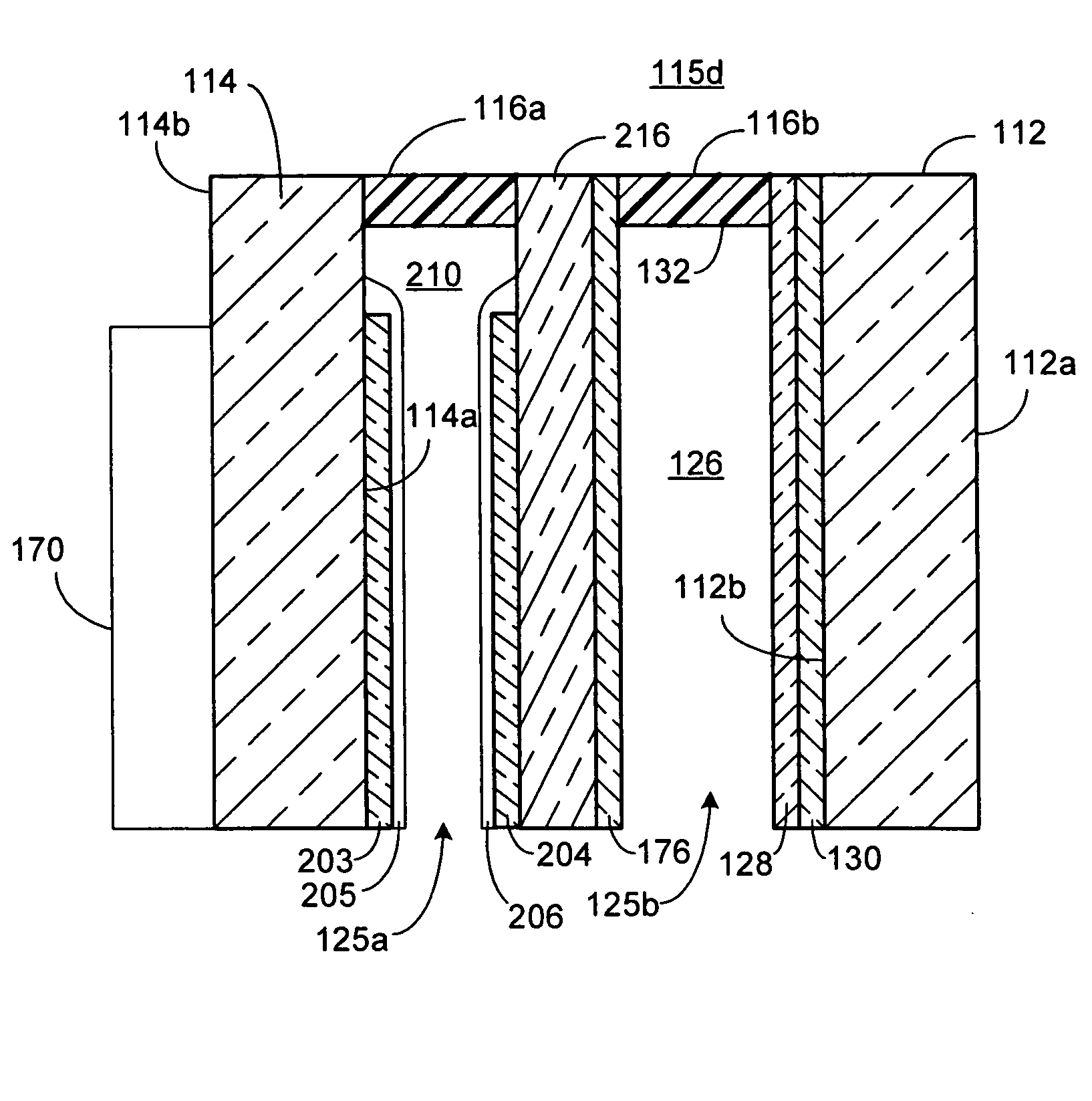
[0152]FIG. 15 shows a window 1000 constructed in accordance with the present invention. Window 1000 comprises a frame 1002, a first transparent substrate 1012, and a second transparent substrate 1014, which serve as the substrates for a cholesteric element 1020. Cholesteric element 1020 has first and second transparent electrodes 1023 and 1024 provided on respective substrates 1012 and 1014. In addition, cholesteric element 1020 includes orientation layers 1025 and 1026 provided on respective transparent electrodes 1023 and 1024 and a seal 1027. A mixture 1030 of of polymerizable, cholesteric liquid crystalline molecules are provided within chamber 1028. Further details of the construction of a suitable cholesteric element is disclosed in U.S. Pat. Nos. 5,762,823 and 5,798,057, the entire disclosures of which are incorporated herein by reference.

[0153]FIG. 16 shows a first embodiment of an insulated window 1100 constructed in accordance with the present invention. Insulated window 1...

second embodiment

[0154]FIG. 17 shows an insulated window 1100a constructed in accordance with the present invention. Insulated window 1100a is similar to insulated window 1100 except that a second cholesteric element 1020a is provided between panes 1112 and 1114. This provides the benefits discussed above. In this embodiment, the first and second cholesteric elements are adjacent one another and share substrate 1132.

third embodiment

[0155]FIG. 18 shows an insulated window 1100b constructed in accordance with the present invention. Insulated window 1100b is similar to insulated window 1100a except that the second cholesteric element 1020a is provided adjacent pane 1114 such that pane 1114 acts as one of the substrates for element 1020a. The insulated chamber 1035 is thus provided between cholesteric elements 1020 and 1020a. It will be appreciated that for some applications, it may be beneficial to replace the second cholesteric element 1020a with an electrochromic element to provide heat absorption and radiation during winter months.

[0156]FIG. 19 shows a vehicle window / sunroof 1200 comprising a cholesteric element 1020 and a shatterproof transparent substrate 1212, which may be made of polyvinylbutrate (PVB), or the like. Cholesteric element 1020 may be provided on either the inside or outside of substrate 1212.


PUM


Abstract

Various structures for variable reflectance rearview mirrors and variable transmittance windows are disclosed. One embodiment pertains to the provision of a polarized reflector in a rearview mirror. Another embodiment pertains to the provision of a switchable cholesteric liquid crystal element in a window. Yet another embodiment pertains to the provision of a plurality of apertures in a reflector layer of a rearview mirror where the apertures are sized and positioned in alignment with light emitting areas of a display positioned behind the reflector layer. In another embodiment, a moveable display or mirror element is attached to a rearview mirror housing.

Description

CROSS-REFERENCE TO RELATED APPLICATION [0001] This application claims priority under 35 U.S.C. §119(e) to U.S. Provisional Application No. 60 / 587,113 filed on Jul. 12, 2004, the entire disclosure of which is incorporated herein by reference.BACKGROUND OF THE INVENTION [0002] The present invention generally pertains to a rearview mirror assembly for a vehicle and to windows (both architectural and vehicular). More particularly, the present invention pertains to a rearview mirror assembly incorporating an electronic device such as a display, light source, and / or light sensor, and to windows having a variable transmittance. [0003] It is desirable to provide electronic devices such as displays, sensors, signal lights, and indicator lights in a rearview mirror assembly of a vehicle. There are several issues with designing a rearview mirror assembly incorporating such an electronic device, particularly when the rearview mirror assembly is an inside mirror assembly. If the electronic devic...

Claims


Application Information

Patent Timeline
Patent Type & Authority Applications(United States)
IPC IPC(8): G02B17/00
CPCB60R1/088
Inventor TONAR, WILLIAM L.BAUER, FREDERICK T.WATSON, ALAN R.
Owner GENTEX CORP
Learn More