Label printer

a label printer and label technology, applied in the field of label printers, can solve the problems of difficult label-dispensing mode change, printer cover must be opened, printers cannot recognize the peeling mode, etc., and achieve the effect of easy chang

Active Publication Date: 2006-01-12
SEIKO EPSON CORP
View PDF5 Cites 16 Cited by
  • Summary
  • Abstract
  • Description
  • Claims
  • Application Information

AI Technical Summary

Benefits of technology

[0015] The present invention is directed to solving the foregoing problem, and an object of this invention is to provide a label printer whereby the paper transportation path can be easily changed in a small opening and closing space when changing the label dispensing mode, and printed labels are not wasted when the operator changes the label dispensing mode as desired.

Problems solved by technology

Whether the label paper is installed in the paper transportation path for the non-peeling mode or the peeling mode cannot, however, be recognized by a printer according to the prior art.
This method makes changing the label-dispensing mode difficult, however, when the label-dispensing mode must be changed on site where the labels are printed.
The trouble with this printer cover is that the printer cover must be opened completely even to simply change the paper transportation path, and thus the label-dispensing mode, without changing the label paper.
This is particularly a problem when the cover is large because a large space is required to open and close the cover.
The labels are thus printed in the wrong mode if the operator loads the label paper in the wrong transportation path, and the resulting labels are thus typically wasted.
This could result in an entire roll of labels being wasted if a large number of labels is dispensed.

Method used


Image

  • Label printer
  • Label printer
  • Label printer

Examples


first embodiment

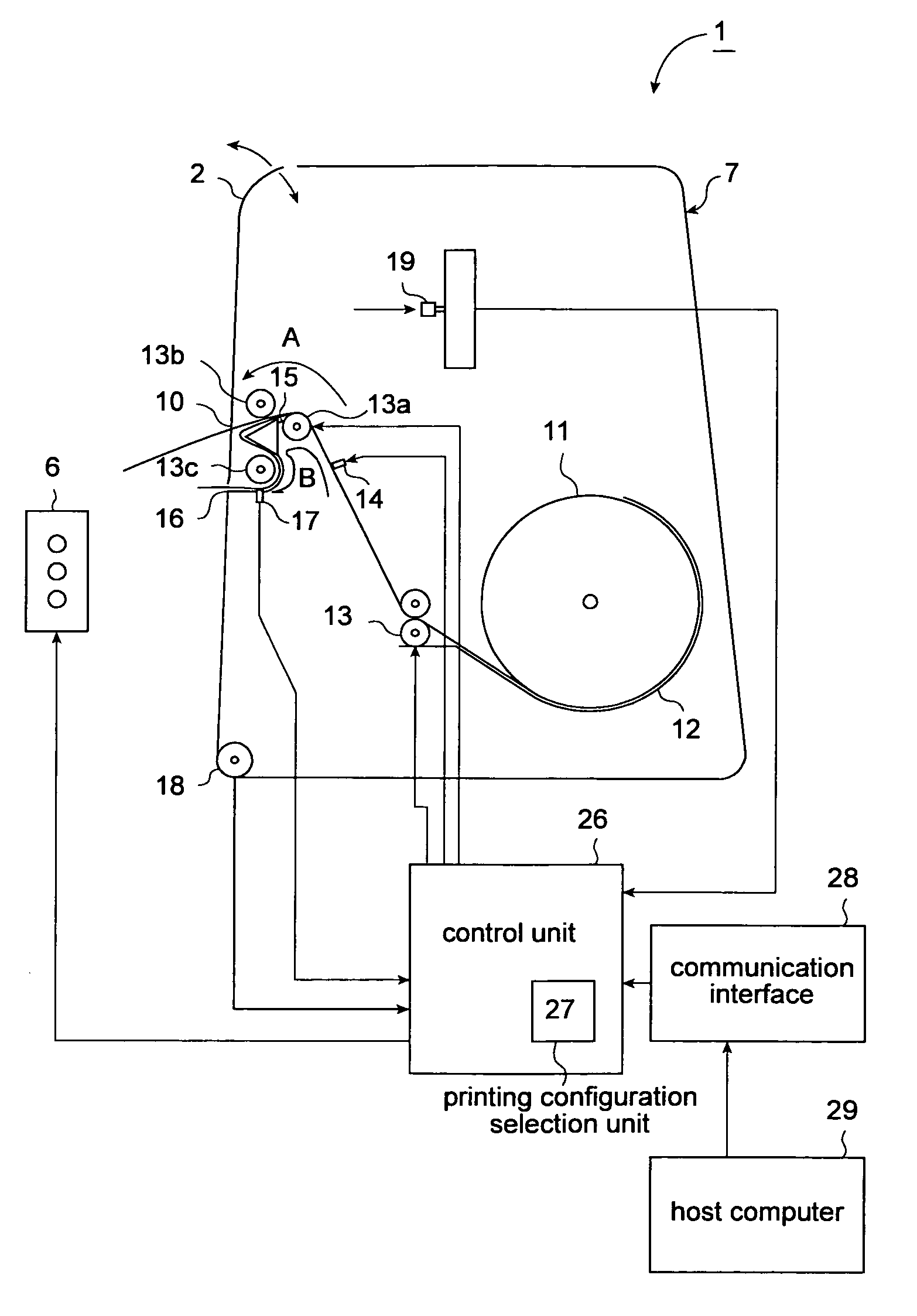
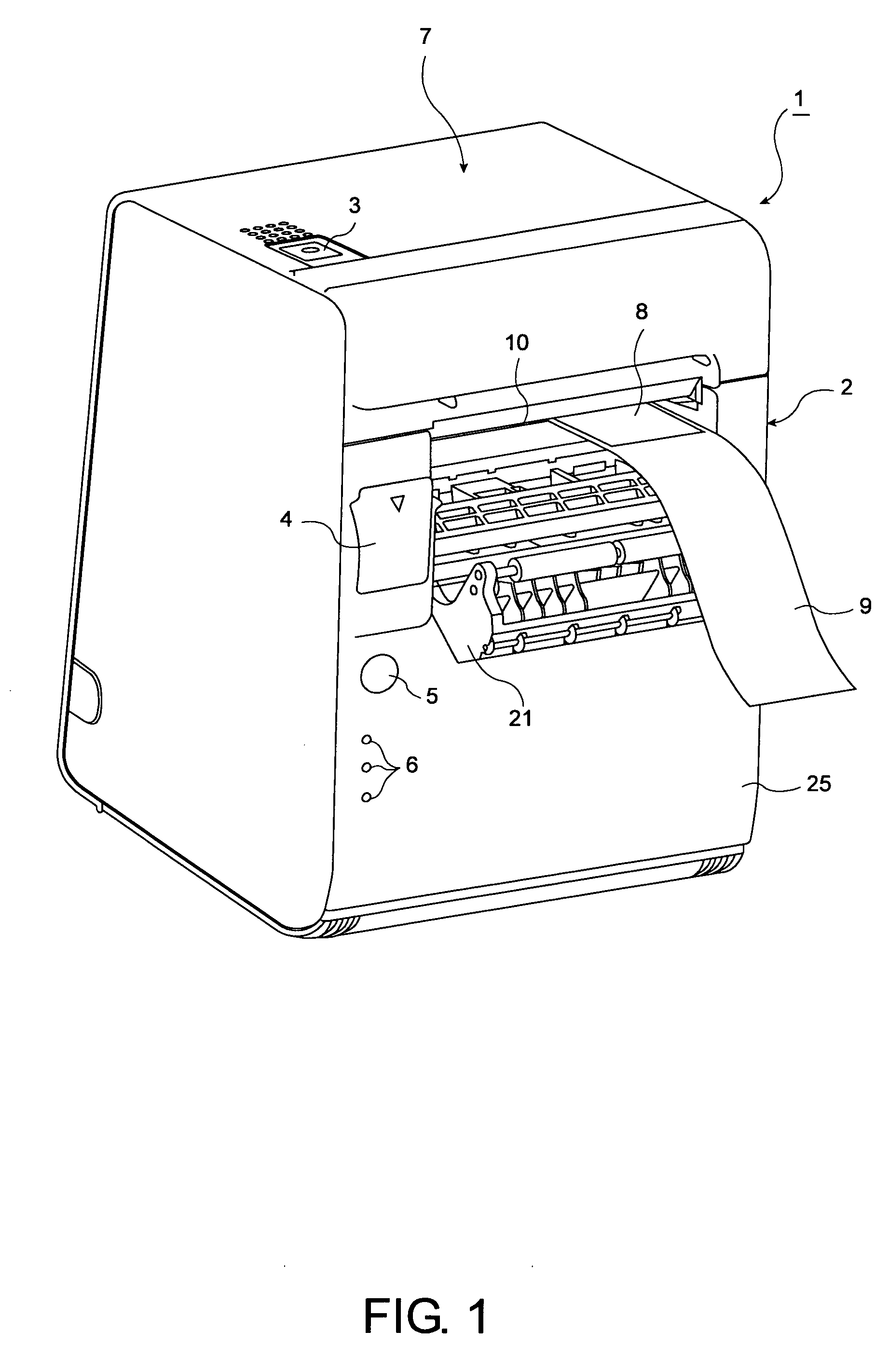
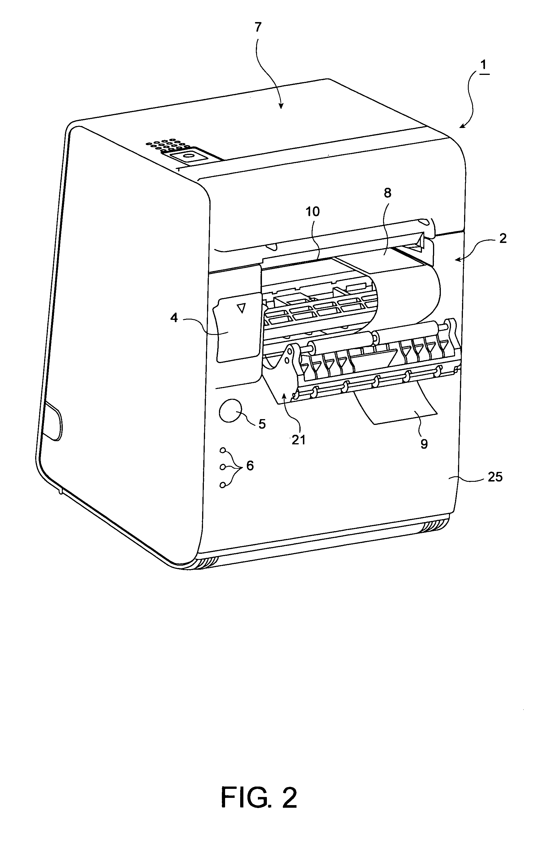
[0062] As shown in FIG. 1 to FIG. 3, a label printer 1 according to the present invention has a cover unit 2 assembled on the front of the printer housing 7 so that the cover unit 2 can open up the front of the printer housing 7. A power switch 3, cover opening switch 4, and feed switch (label feed switch) 5 are positioned on the surface of the printer housing 7. A display unit 6 with paper out, error, and power indicators (LEDs) is also provided so that the operating status of the label printer 1 can be determined.

[0063] The cover unit 2 is composed of a printer cover 25 and a peeling unit (label-peeling mechanism) 21.

[0064] The peeling unit 21 is axially supported so that the peeling unit 21 can pivot at the top edge of the printer cover 25. As shown in FIG. 1, the peeling unit 21 can be pulled out to the front from the printer cover 25.

[0065] When in the peeling configuration (peeling mode) with the web 9 of the label paper 11 passing through the second paper transportation pat...

second embodiment

[0105] A label printer 101 according to this second embodiment of the invention uses a slide switch 119 as the mode selection switch.

[0106] A window 124 is formed in the top of the printer cover 125 portion of the cover unit 102 so that the position of the slide switch 119 can be viewed through the window 124 when the cover unit 102 is closed. In addition, the slide switch 119 cannot be physically accessed when the cover unit 102 is closed.

[0107] The printer cover 125 can be opened after opening the peeling unit 121 in a label printer 101 according to this second embodiment of the invention. Opening the printer cover 125 also causes the label printer 101 to go off-line.

[0108] This label printer 101 is controlled in the same way as the label printer 1 according to the foregoing first embodiment of the invention.

[0109]FIG. 11 is a flow chart of a process for changing the printing configuration by means of the slide switch 119. Like steps in FIG. 11 and the flow chart in FIG. 7 (b) ...

third embodiment

[0111]FIG. 12 to FIG. 15 are external oblique views of a label printer according to the invention. FIG. 16 and FIG. 17 are side section views showing the major internal arrangement of the label printer. FIG. 18 to FIG. 21 are side section views showing the relationship between the shutter and the printer cover release lever when the peeling unit release lever is operated. FIG. 22 describes the differences between the web transportation paths in the different label dispensing modes.

[0112] As shown in FIG. 12 to FIG. 16, a label printer 201 according to this third embodiment of the invention has a long box-like printer housing 202. A printer cover 203 (cover unit) is attached to the front of the printer housing 202 so that the printer cover 203 can be freely opened and closed. Opening the printer cover 203 opens the roll paper compartment 204, that is, the label paper compartment, inside the printer housing 202 so that label paper 300 can be loaded into the printer.

[0113] The printer...


PUM


Abstract

In a label printer in which either a peeling mode or non-peeling mode can be selected as the label dispensing mode, labels are printed and thus wasted when the operator loads the label paper into a transportation path that does not match the desired dispensing mode. This problem is solved by a label printer enabling selecting as the printing configuration either a peeling configuration for peeling printed labels from the web of label paper 11, or a non-peeling configuration in which the printed labels are not separated from the web of the label paper 11. A printing configuration selection unit 27 enables selecting which printing configuration to use. To operate in the non-peeling mode, the label paper 11 is loaded into a first paper transportation path A. To operate in the peeling mode, the label paper 11 is loaded to a second paper transportation path B. A cover unit 2 can be opened and closed to enable handling the label paper, and takes the label printer off-line when the cover unit 2 is opened. A mode selection switch 19 is accessible only when the cover unit is open and operating the mode selection switch causes the printing configuration selection unit 27 to change the printing configuration.

Description

BACKGROUND OF THE INVENTION [0001] 1. Field of the Invention [0002] The present invention relates to a label printer having a label peeling mechanism for peeling printed labels from the web liner. [0003] 2. Description of the Related Art [0004] Label printers for printing and peeling labels from the web liner on which the labels are carried are known from the literature. The label printer taught in Japanese Unexamined Patent Appl. Pub. H08-295323 (corresponding to U.S. Pat. No. 5,980,138), for example, conveys label paper having adhesive labels of a known constant length affixed to a web past a printing unit whereby the labels are printed. This label printer then conveys the printed label paper at an acute angle though a label peeling unit to sequentially peel the labels one by one from the web and dispense the printed peeled labels from a dispenser opening while detecting the labels with a peeled label detector. [0005] This mode of printing and peeling the labels one by one is refe...

Claims


Application Information

Patent Timeline
Patent Type & Authority Applications(United States)
IPC IPC(8): B41J15/04B41J15/16B41J29/42
CPCB41J3/4075B41J15/042B41J11/0095
Inventor MIYASAKA, MASAYOHIROIKE, GOFUKANO, KAZUKOTAKAMI, TORUYAMADA, KOJI
Owner SEIKO EPSON CORP
Why Eureka
Try Eureka