Bone plate and bone screw system

a bone screw and bone plate technology, applied in the field of orthopedic implants, can solve the problems of preventing proper bone healing, requiring surgery, and the system is, then, fairly complex

Inactive Publication Date: 2006-01-12
SPEIRS ANDREW +1
View PDF5 Cites 265 Cited by
  • Summary
  • Abstract
  • Description
  • Claims
  • Application Information

AI Technical Summary

Problems solved by technology

A loose bone plate can prevent proper healing of a bone, and may require surgery for removal.
This system is, then, fairly complex and relies on locking elements that are separate and distinct from the bone screws.
This is not practical, because to engage the fine screw threads which are set close together, the screw must be turned a number of times without substantially advancing in the bone.
This may damage the bone.

Method used


Image

  • Bone plate and bone screw system
  • Bone plate and bone screw system
  • Bone plate and bone screw system

Examples


Embodiment Construction

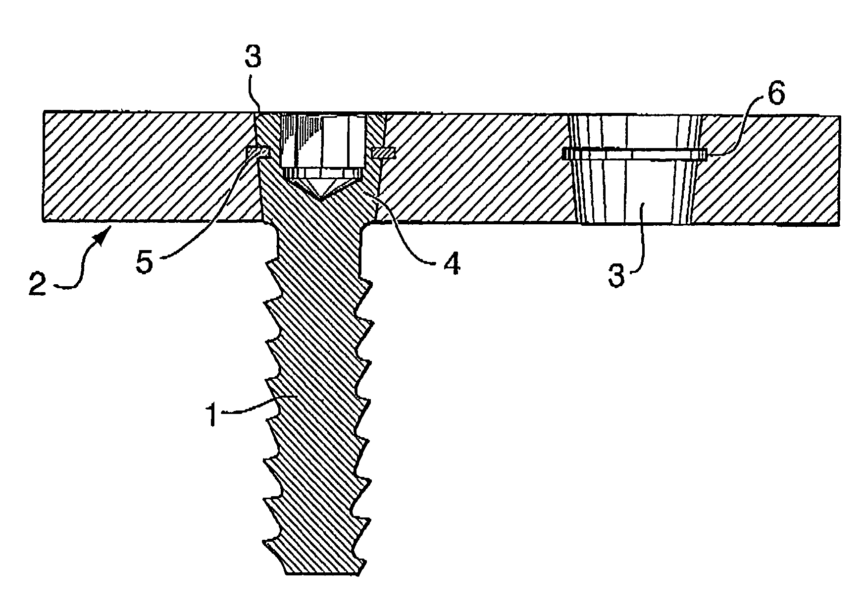
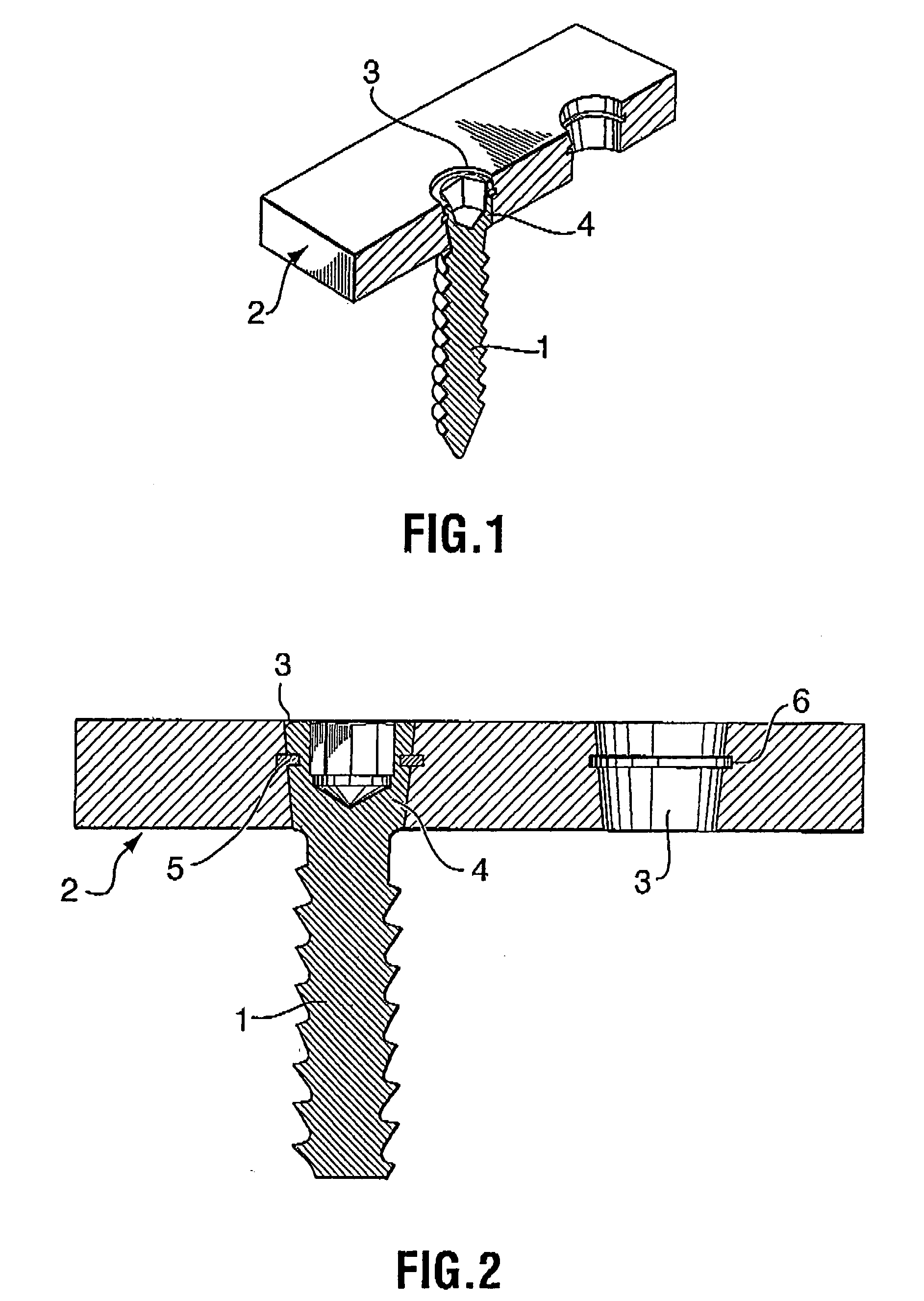
[0018] As can be seen in FIGS. 1 and 2, the present invention provides a bone screw 1 in combination with a bone plate 2. The bone plate 2 shown in FIG. 1 is a simple rectangle for illustrating purposes only. In fact, bone plates are typically produced in a variety of shapes for a variety of applications. The bone plate essentially is a fairly low profile metallic piece, with two or more screw holes formed in it. It may be fairly long, for use in repairing long bones such as the tibia, or it may be short. The plate may be narrow, i.e., one screw hole wide, or it may span several screw holes if designed for repair of wide flat bones such as the pelvis or scapula. It may be T-shaped, L-shaped, spoon shaped, or be pre-contoured or bent into a specific shape by a surgeon. It will be appreciated, then, that the small rectangular representation of a bone plate shown in this application is by no means meant to be exhaustive. Moreover, it will be understood that it is not necessary, in orde...


PUM


Abstract

A bone screw having a head portion and a threaded shaft extending therefrom is described. The head portion has a top surface with a drive means formed therein coaxial with the threaded shaft and a profiled portion between the top surface and the threaded shaft. The profiled portion of the body is provided with a circumferential groove on its surface, substantially coaxial with the threaded shaft.

Description

FIELD OF THE INVENTION [0001] The present invention relates to the field of orthopedic implants, and in particular, provides a bone plate and bone screw system in which the bone screws, when fully screwed into place, become locked in position relative to the bone plate. BACKGROUND OF THE INVENTION [0002] In traditional bone plate / bone screw systems, the plate is shaped to fit a particular bone or type of bone (e.g., a long bone) and a series of holes are pre-formed through the plate, so that the plate may be fastened to a bone that requires repair by two or more bone screws. It is typical that the plates are partially spherically counterbored around the screw holes, and the bore screws will have heads with substantially matching profiles, so that the screw heads will, when driven home, be countersunk into the surface of the bone plate and may be angled somewhat relative to the bone plate by virtue of the partially spherically counterbore and complementary screw head. [0003] In order...

Claims


Application Information

Patent Timeline
Patent Type & Authority Applications(United States)
IPC IPC(8): A61B17/56A61B17/80
CPCA61B17/8061A61B17/8047
Inventor SPEIRS, ANDREWDESJARDINS, RAYMOND
Owner SPEIRS ANDREW
Why Eureka
Try Eureka