Method and apparatus for disk array based I/O routing and multi-layered external storage linkage

a disk array and multi-layered technology, applied in the field of storage systems, can solve problems such as performance degradation, physical separation and independent non-replies may be problematic, and system cannot access data including the replicated data in the second storage system

Active Publication Date: 2006-01-12
HITACHI LTD
View PDF6 Cites 144 Cited by
  • Summary
  • Abstract
  • Description
  • Claims
  • Application Information

AI Technical Summary

Benefits of technology

[0010] A system and method for linking external storage systems that includes creating a virtual volume mapping at one or more storage systems. Each virtual volume mapping at each storage system associating a virtual storage volume with a physical storage volume and/or one second virtual storage volume at one or more second storage systems. An access request is received at a first storage system specifying a virtual volume. It is determined on which storage system a phys...

Problems solved by technology

If these servers shared one SAN architecture, performance degradation may occur.
However, in systems where security or Input/Output (I/O) performance is not as high a priority, physically separated and independent SANs may be problematic.
This is problematic in that sometimes there may be a requirement that the servers in SAN_A have access to storage systems in SAN_B, and vice versa.
Some current SAN systems replicate data from a first storage system to a second storage system via a network, however, a server from one storage system cannot access data including the replicated data in the second storage system.
Data access from a server that is connected to one VSAN to a storage system that is connected to another VSAN is restricted.
However, this is problematic in that even if a user has physical SANs in different locations, VSAN requires a user to connect these physical SANs to one big physical SAN.
Further, such communications over long distance...

Method used

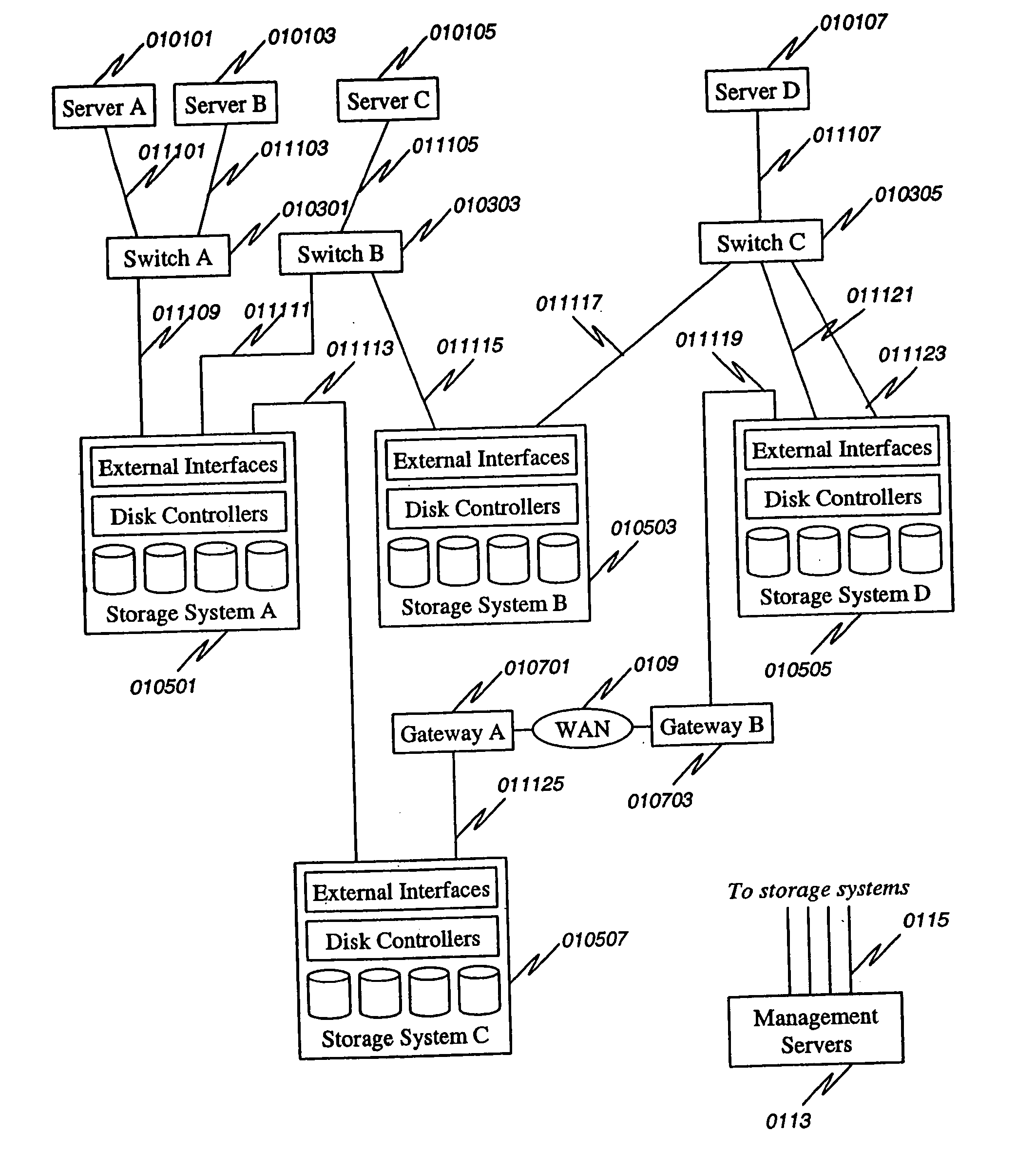
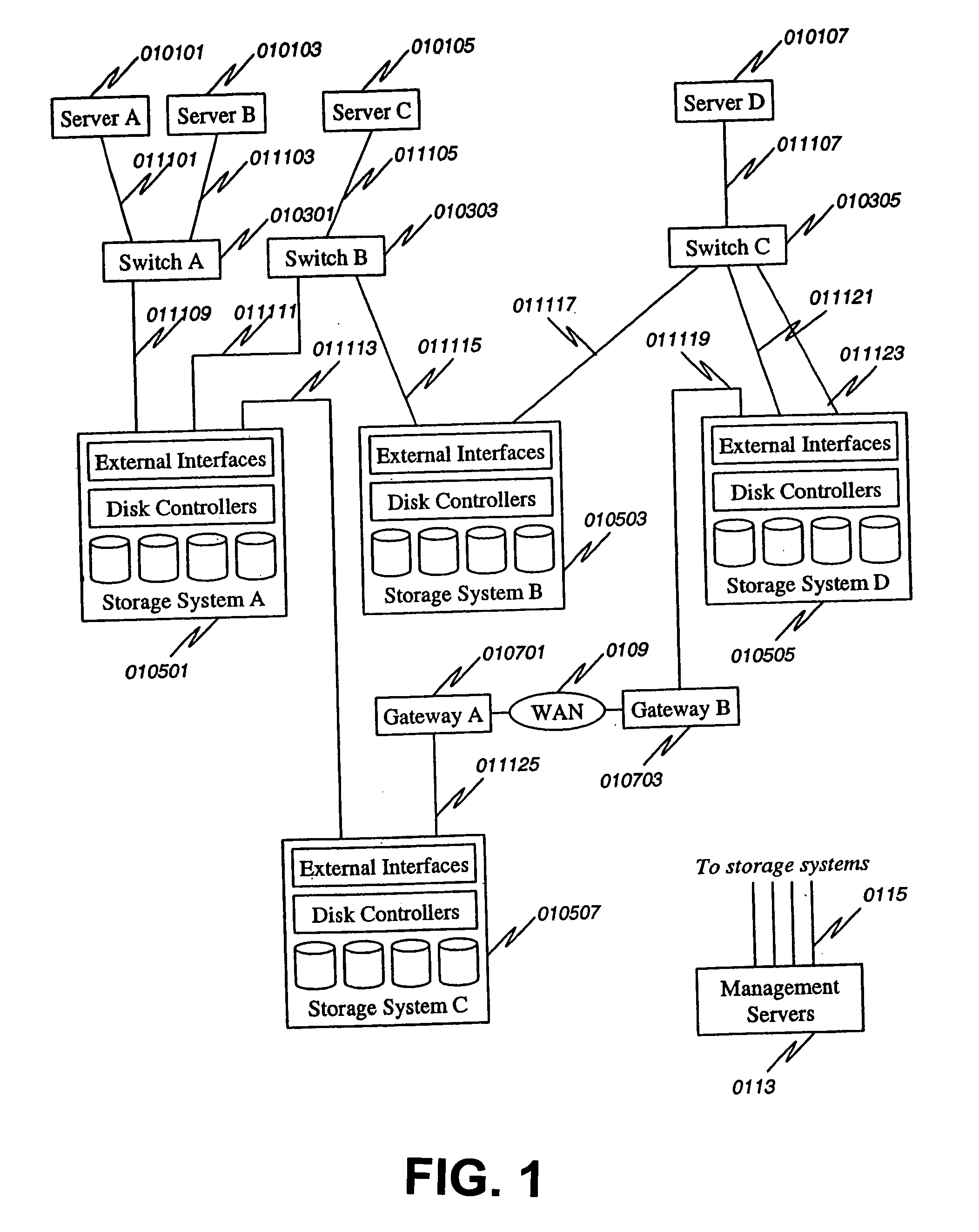
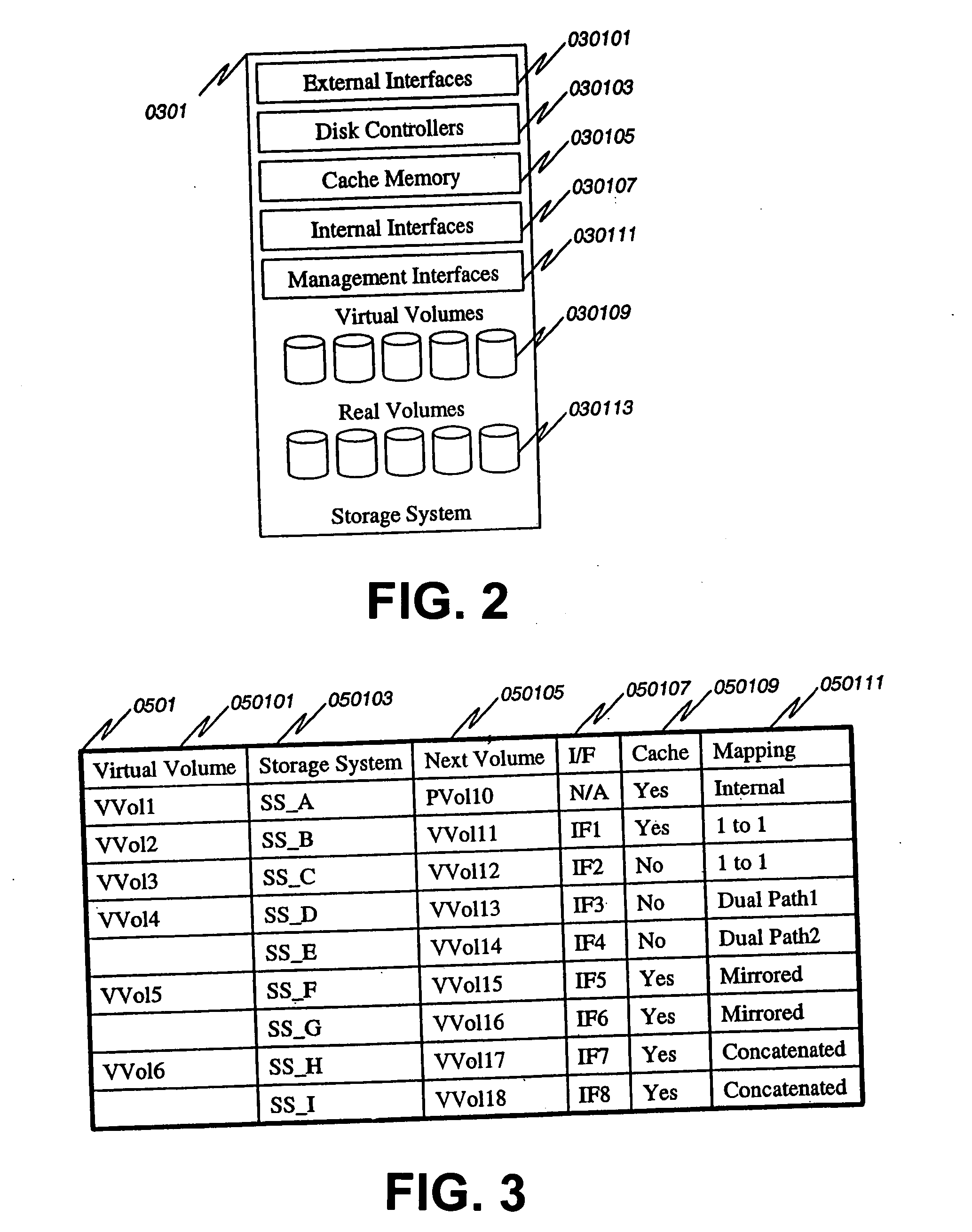

Image

  • Method and apparatus for disk array based I/O routing and multi-layered external storage linkage
  • Method and apparatus for disk array based I/O routing and multi-layered external storage linkage
  • Method and apparatus for disk array based I/O routing and multi-layered external storage linkage

Examples


Embodiment Construction

[0038] The particulars shown herein are by way of example and for purposes of illustrative discussion of the embodiments of the present invention. The description taken with the drawings make it apparent to those skilled in the art how the present invention may be embodied in practice.

[0039] Further, arrangements may be shown in block diagram form in order to avoid obscuring the invention, and also in view of the fact that specifics with respect to implementation of such block diagram arrangements is highly dependent upon the platform within which the present invention is to be implemented, i.e., specifics should be well within purview of one skilled in the art. Where specific details (e.g., circuits, flowcharts) are set forth in order to describe example embodiments of the invention, it should be apparent to one skilled in the art that the invention can be practiced without these specific details. Finally, it should be apparent that any combination of hard-wired circuitry and soft...


PUM


Abstract

A system and method for linking external storage systems that includes creating a virtual volume mapping at one or more storage systems. Each virtual volume mapping at each storage system associating a virtual storage volume with a physical storage volume and/or one second virtual storage volume at one or more second storage systems. An access request is received at a first storage system specifying a virtual volume. It is determined on which storage system a physical storage volume associated with the specified virtual volume in the access request is located using the virtual volume mapping at the first storage system and/or the virtual volume mapping at one or more second storage systems. Access is provided to the physical storage volume based on which storage system the physical storage volume is located. Useful in Storage Area Networks and many configurations including 1 to 1, dual path, mirrored, and concatenated, etc.

Description

BACKGROUND [0001] 1. Field of the Invention [0002] This invention relates to storage systems, and more specifically to routing of I / O requests to an appropriate storage system via virtual storage volume mapping in Storage Area Network (SAN) systems. [0003] 2. Description of the Related Art [0004] Storage area networks (SANs) provide a solution for storing and retrieving mass amounts of data. A typical SAN network architecture may consist of one or more host devices interconnected to one or more network devices or switches through an interface. The network devices or switches may then be interconnected to one or more data storage devices through a second network or interface. Many SAN architectures use Fibre Channel (FC) as the interface or network, however, Ethernet, Infiniband, Internet, and other networks / interfaces may also be used in a SAN architecture. [0005] In an SAN system, there may be one or more physically separated and independent SANs. Physically separated and independe...

Claims


Application Information

Patent Timeline
IPC IPC(8): G06F11/00
CPCG06F3/0605G06F3/0631G06F3/0662G06F3/067G06F11/2094G06F11/0787G06F11/201G06F11/2076G06F11/0727
Inventor KODAMA, SHOJI
Owner HITACHI LTD
Why Eureka
Try Eureka