Ergotube and inverted microscope having an ergotube

a technology of inverted microscope and ergotube, which is applied in the field of ergotube, can solve the problems of limited space for additional optical elements that are to be moved into the beam path in motorized or mechanical fashion, and achieve the effect of reducing the number of reflections

Inactive Publication Date: 2006-01-19
LEICA MICROSYSTEMS CMS GMBH
View PDF16 Cites 2 Cited by
  • Summary
  • Abstract
  • Description
  • Claims
  • Application Information

AI Technical Summary

Benefits of technology

[0008] It is the object of the invention to create an ergotube which possesses a variable viewing angle, has a shallow overall depth, and minimizes the number of reflections for deflection of the microscope beam path into the eyepiece.
[0010] A further object of the invention is to create an inverted microscope which makes available sufficient room for the installation or addition of further motorized microscope functions or motorized microscope components and is ergonomically operable by the user, and in which incoupling of the microscope beam path into the eyepiece of the ergotube requires a minimum number of reflections.
[0012] The invention has the advantage that in an ergotube which encompasses an eyepiece that defines an eyepiece beam path, incoupling of the tube beam path or microscope beam path into the eyepiece is accomplished with a minimum number of reflections. The ergotube is equipped, in addition to the eyepiece (which can be configured as a binocular eyepiece), with a tube housing into which the tube beam path or microscope beam path enters. The ergotube is further equipped with an installation element for mounting it on the microscope stand. Arranged in the tube housing is a mirror that has a mirror surface and deflects the tube beam path or microscope beam path into the eyepiece beam path. The eyepiece itself is embodied pivotably about an axis, and upon pivoting of the eyepiece through an angle α, the mirror is concurrently pivoted through an angle α / 2. A cylindrical holding element for the mirror is provided on the axis. The mirror itself is the only deflection element arranged in the tube housing. The mirror itself is installed in the holding element in such a way that the axis extends centeredly on the mirror surface.

Problems solved by technology

The V-shaped beam path in an inverted microscope has the disadvantage that the space for additional optical elements that are to be moved into the beam path in motorized or mechanical fashion is limited.

Method used


Image

  • Ergotube and inverted microscope having an ergotube
  • Ergotube and inverted microscope having an ergotube
  • Ergotube and inverted microscope having an ergotube

Examples


Embodiment Construction

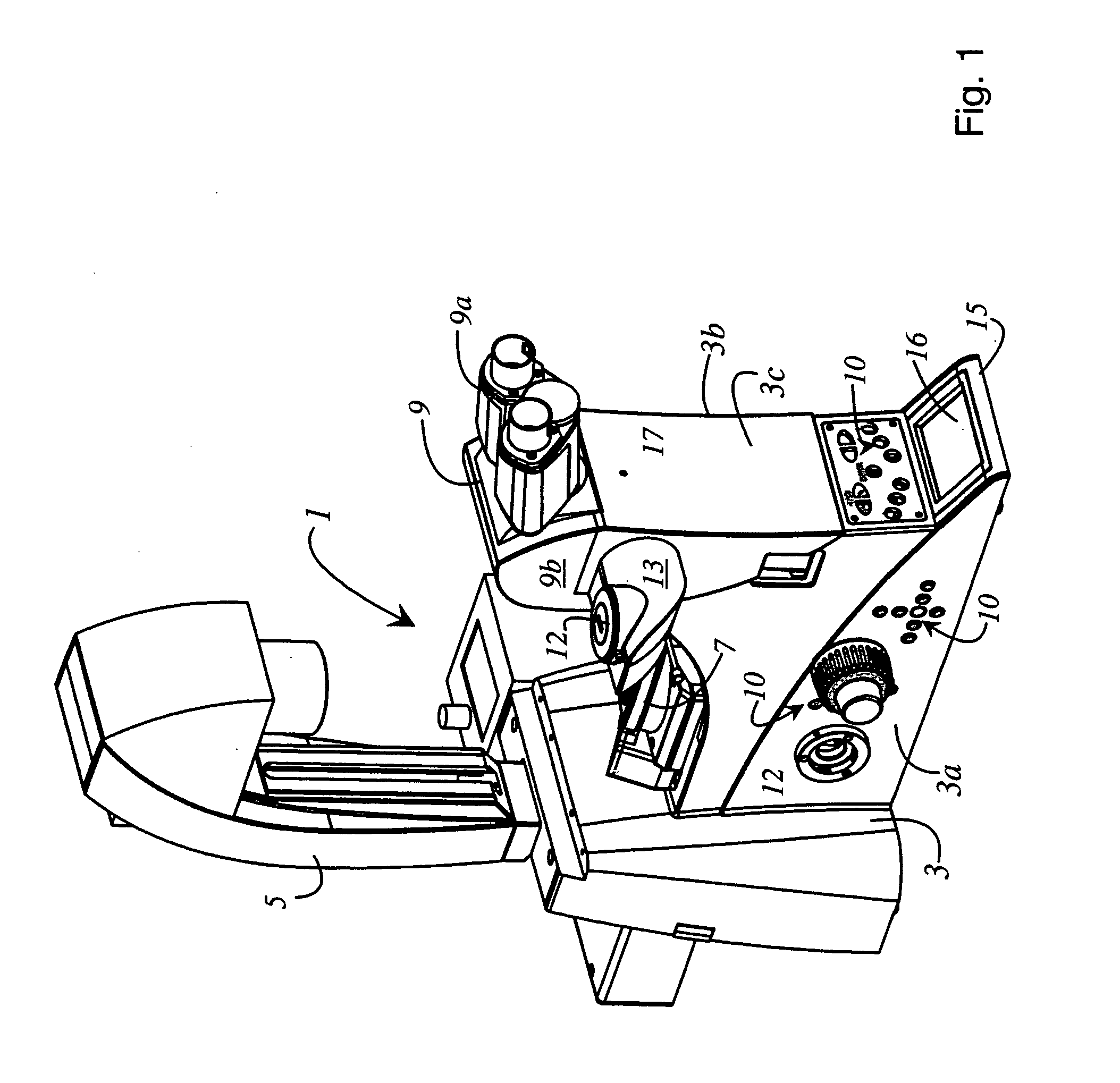
[0027]FIG. 1 is a perspective view of an inverted microscope 1 in which the subject matter of the invention is implemented. Inverted microscope 1 comprises a base stand part 3 and an illumination stand part 5 placed on base stand part 3. Base stand part 3 encompasses a first side surface 3a, a second side surface 3b, and a front surface 3c. Base stand part 3 likewise carries an ergotube 9 opposite illumination stand part 5. Ergotube 9 comprises an eyepiece 9a and a tube housing 9b. In this embodiment, eyepiece 9a is embodied as a binocular eyepiece. Mounted on tube housing 9b is a lateral outlet 13 that is equipped with a port 12. The user can connect, for example, a camera, an evaluation device, etc. to port 12. Between illumination stand part 5 and tube 9, base stand part 3 carries a revolving nosepiece 7 with which at least one objective (not depicted) can be introduced into the microscope beam path. In addition to port 12 provided on lateral outlet 13, further ports 12 are embod...


PUM


Abstract

An inverted microscope (1) equipped with an ergotube (9) is disclosed. The ergotube (9) substantially comprises an eyepiece (9a) and a tube housing (9b). The microscope beam path (30) defined by the inverted microscope (1) is of U-shaped configuration. The U-shaped microscope beam path (30) is deflected into the eyepiece (9a) by a single deflection element (74) that is embodied as a pivotable mirror.

Description

RELATED APPLICATIONS [0001] This application claims priority of the German patent application 10 2004 034 846.4 which is incorporated by reference herein. FIELD OF THE INVENTION [0002] The invention concerns an ergotube. The invention concerns in particular an ergotube which encompasses an eyepiece that defines an eyepiece beam path. The ergotube further encompasses a tube housing that defines a tube beam path. The ergotube is equipped with an installation element in order to mount the ergotube on a microscope stand. A mirror equipped with a mirror surface deflects the tube beam path into the eyepiece beam path, the eyepiece being embodied pivotably about an axis. Upon pivoting of the eyepiece through an angle α, the mirror pivots about an angle α / 2. BACKGROUND OF THE INVENTION [0003] The invention further concerns an inverted microscope having an ergotube. The invention concerns in particular an inverted microscope having an ergotube that comprises an eyepiece and a tube housing. T...

Claims


Application Information

Patent Timeline
Patent Type & Authority Applications(United States)
IPC IPC(8): G02B21/00G02B21/20
CPCG02B21/20G02B21/0088G02B21/24
Inventor EUTENEUER, PETERKRUGER, RALF
Owner LEICA MICROSYSTEMS CMS GMBH
Why Eureka
Try Eureka