
Optical transmission system and method of controlling optical transmission system

a transmission system and optical transmission technology, applied in the field of optical transmission systems and a control method of optical transmission systems, can solve the problems of chromatic dispersion, greatly degraded optical signal characteristics, and deterioration of pulse waveforms, and achieve high-precision dispersion compensation and increase optical transmission quality.

Inactive Publication Date: 2006-01-19
FUJITSU LTD
View PDF24 Cites 9 Cited by
  • Summary
  • Abstract
  • Description
  • Claims
  • Application Information

AI Technical Summary

Benefits of technology

[0025] It is therefore an object of the present invention to provide an optical transmission system which is capable of performing highly accurate dispersion compensation for increased optical transmission quality with respect to many various network configurations having a plurality of paths including OADM nodes and HUB nodes in the system.

Problems solved by technology

Therefore, when a pulse of light is transmitted over an increased distance, it suffers chromatic dispersion which deteriorates the pulse waveform.
If the waveform of a transmitted optical signal is deteriorated by chromatic dispersion in the WDM system for high-speed large-capacity optical transmission, the characteristics of the received optical signal are greatly degraded, adversely affecting the WDM system.
Consequently, there is also a limit posed on the reduction of the optical power, i.e., a lower limit on the optical power.
If a chromatic dispersion value deviates from the RD tolerance, then it cannot be ensured that the reception side can identify signals “0”, “1” from each other, i.e., the deterioration of the eye aperture becomes so large that it is difficult to identify the data.
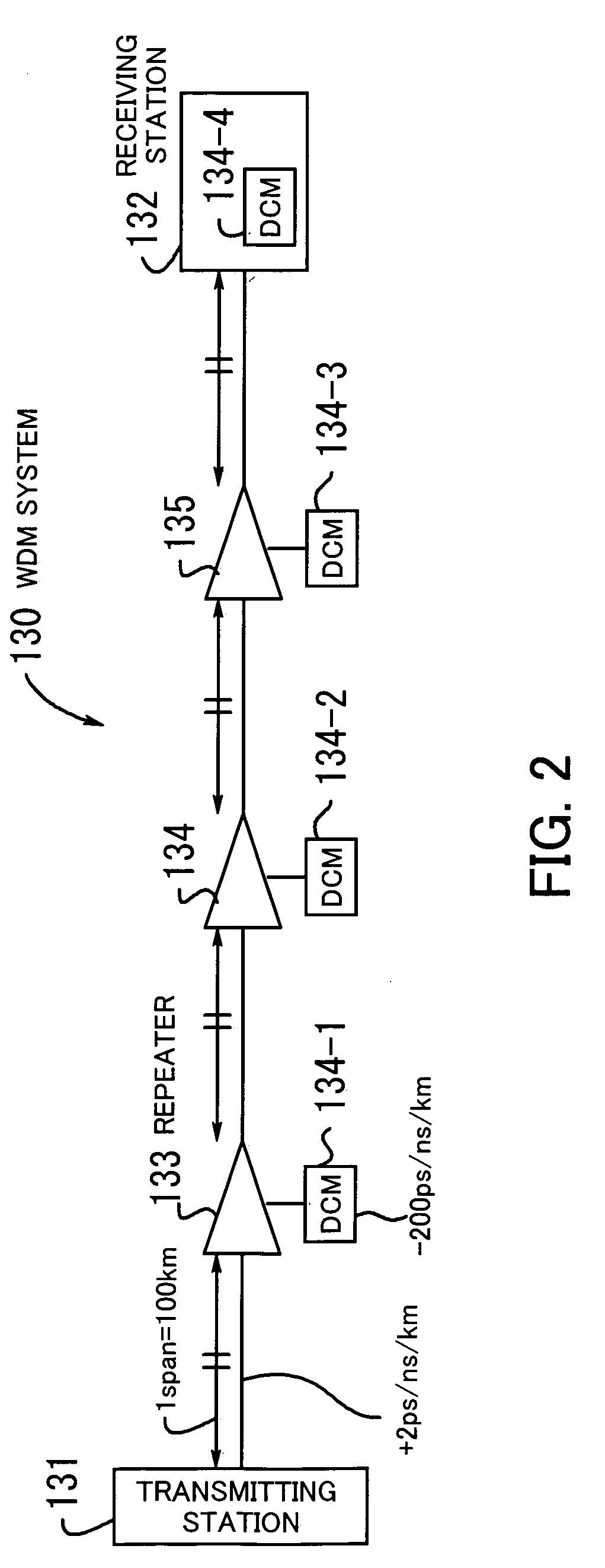
In actually constructed systems, however, optical repeaters cannot be positioned at equal spans, and the spans have different distances and hence cause different losses.
Consequently, each of the spans is not optimized for OSNR (Optical S / N Ratio) and nonlinear quantity.
Moreover, the conventional system designing process is problematic in that if a WDM system is constructed as a network including an OADM (Optical Add Drop Multiplex) node or a HUB node in order to optimize itself for a dispersion map of a long-distance through path, a path interconnecting terminal stations, the transmission performance is greatly deteriorated with respect to new paths other than the through path which are produced by the OADM node or the HUB node.

Method used


Image

  • Optical transmission system and method of controlling optical transmission system
  • Optical transmission system and method of controlling optical transmission system
  • Optical transmission system and method of controlling optical transmission system

Examples


first embodiment

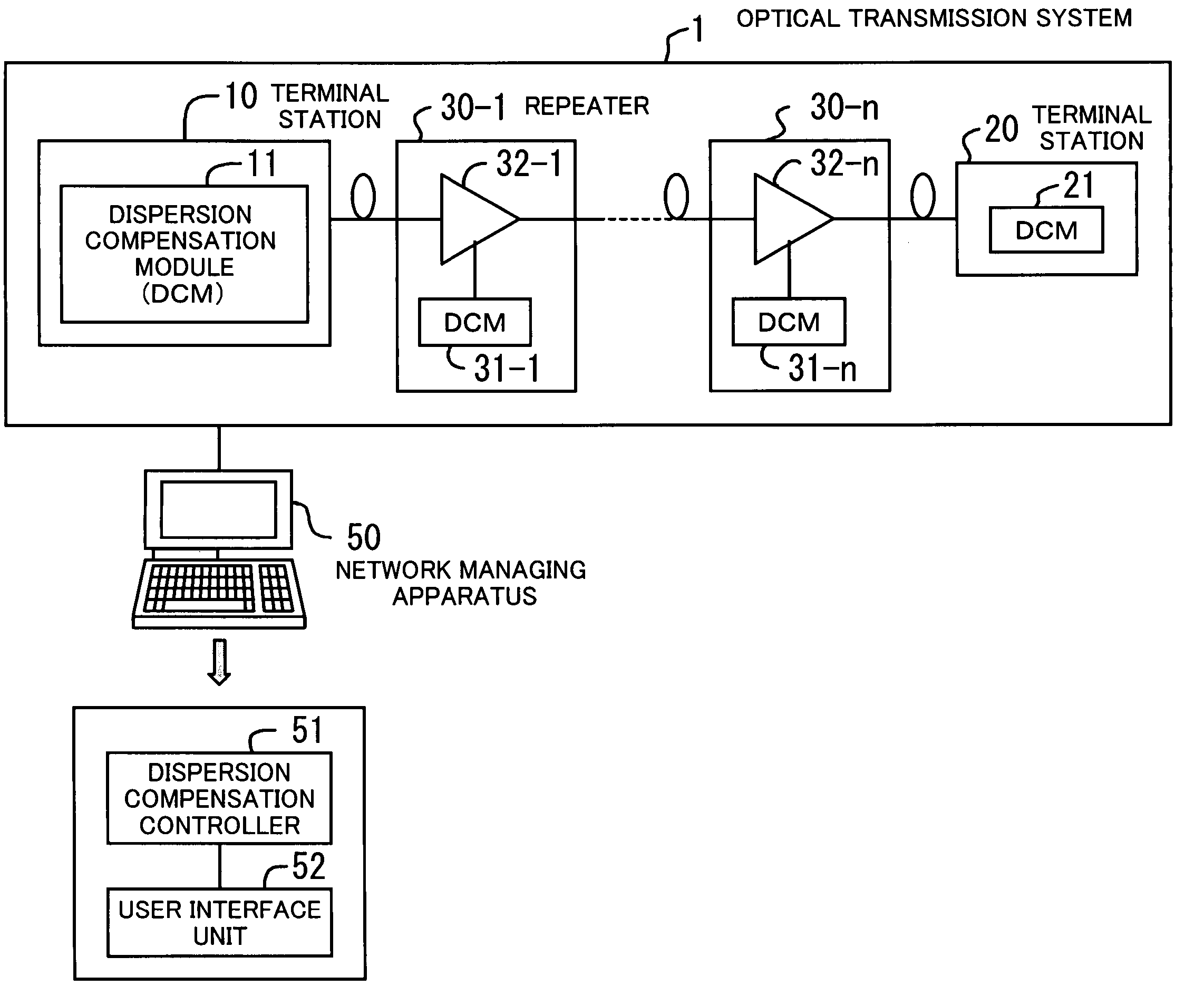
[0095]FIG. 10 shows a processing sequence according to the present invention. The illustrated processing sequence represents an operation flow of the network managing apparatus 50 which is carried out as a dispersion compensation control process for the optical transmission system 1a.

[0096] [S1] A target value φtgt for the nonlinear phase shift which maximizes the residual dispersion tolerance of the through path from terminal to terminal is determined by simulations as shown in FIGS. 7 an 8.

[0097] [S2] A nonlinear phase shift φspan,ave per span is determined according to the following equation (4): ϕ⁢ ⁢span,ave=ϕ⁢ ⁢tgtN(4)

[0098] [S3] A nonlinear phase shift of the span m is assigned to the nonlinear phase shift of the fiber transmission path and the nonlinear phase shift of the DCM according to the following equation (5):

φspan,ave=φFm+φDm  (5)

[0099] [S4] If there is a limitation on the input power applied to the transmission path (e.g., if the input power applied to the transm...

second embodiment

[0105] An OSNR degradation that contributes to the overall system of each span is greater as the input level of a node next to the span is lower. If the optical amplifiers which are responsible for noise are optimized to the respective input levels, then the amount of the OSNR degradation is inversely proportional to the anti-logarithm 10ˆ(−Δpin / 10) (where Δ pin represents a variation with respect to the node input level serving as a reference) of the input level. For example, on the assumption that the loss of each span is not taken into account, if there is a span for transmitting a signal with high power over a zone having a short distance (a loss is small) or a span for transmitting a signal with low power over a zone having a long distance (a loss is large), the input levels of the next nodes are varied greatly, causing a greater OSNR degradation than if all the nodes have the same input level. the input power applied to the transmission path is set such that a signal is trans...

third embodiment

[0117] The terminal station 10 include a MUX 12 and a nonlinear generator 14. The OADM node 61 includes a DMUX 61a, a MUX 61b, and a nonlinear generator 61c (only those components required to describe the third embodiment are shown). The nonlinear generators 14, 61c are connected in each channel, and generate a certain nonlinear phase shift according to an instruction from the network managing apparatus 50.

[0118] It is assumed that a path from terminal to terminal is referred to as a path P1 (the number of spans is N), a path from the terminal station 10 to the OADM node 61 as an OADM path P2 (the number of spans is N1), and a path from the OADM node 61 to the terminal station 20 as an OADM path P3 (the number of spans is N2).

[0119]FIG. 14 shows a processing sequence according to the third embodiment of the present invention. The illustrated processing sequence represents an operation flow of the network managing apparatus 50 which is carried out as a dispersion compensation contro...


PUM


Abstract

A control method, which is applicable to a variety of network configurations, controls an optical transmission system to determine optimum optical input power to a transmission path for increased optical transmission quality. The optical transmission system has terminal stations, repeaters, dispersion compensation modules, and a dispersion compensation controller. The terminal stations transmit and receive an optical signal through an optical fiber transmission path. The repeaters are disposed in the optical fiber transmission path for amplifying the optical signal. The dispersion compensation modules are disposed in the terminal stations and the repeaters for compensating for dispersion of the optical signal. The dispersion compensation controller determines a target value for a nonlinear phase shift, which is an indication of a self-phase modulation caused by a transmission medium of the optical fiber transmission path, to have a maximum residual dispersion tolerance, and adjusts at least one of the input powers applied to transmission paths connected to the terminal stations or the repeaters and the input powers applied to the dispersion compensation modules to equalize the nonlinear phase shifts of paths in the optical transmission system to the target value.

Description

CROSS-REFERENCE TO RELATED APPLICATIONS [0001] This application is based on, and claims priority to, Japanese Application No. 2004-207206, filed on Jul. 14, 2004, in Japan, and which is incorporated herein by reference. BACKGROUND OF THE INVENTION [0002] 1. Field of the Invention [0003] The present invention relates to an optical transmission system and a method of controlling an optical transmission system, and more particularly to a method of controlling an optical transmission system for compensating for chromatic dispersion that is caused when an optical signal is transmitted through an optical fiber, and an optical transmission system for transmitting an optical signal through an optical fiber while compensating for chromatic dispersion. [0004] 2. Description of the Related Art [0005] In recent years, the WDM (Wavelength Division Multiplex) system for multiplexing light rays having different wavelengths to simultaneously transmit a plurality of signals through a single optical ...

Claims


Application Information

Patent Timeline
Patent Type & Authority Applications(United States)
IPC IPC(8): H04B10/12H04B10/07H04B10/2507H04B10/2525H04B10/2531H04B10/29H04B10/296H04J14/00H04J14/02
CPCH04B10/564H04B10/255
Inventor ODATE, KAORISEKIYA, MOTOYOSHIMIYASHITA, TAKUYA
Owner FUJITSU LTD
Learn More