
Developing device, developing cartridge, process cartridge, and image forming apparatus using these

Inactive Publication Date: 2006-01-19
CANON KK
View PDF25 Cites 11 Cited by
  • Summary
  • Abstract
  • Description
  • Claims
  • Application Information

AI Technical Summary

Benefits of technology

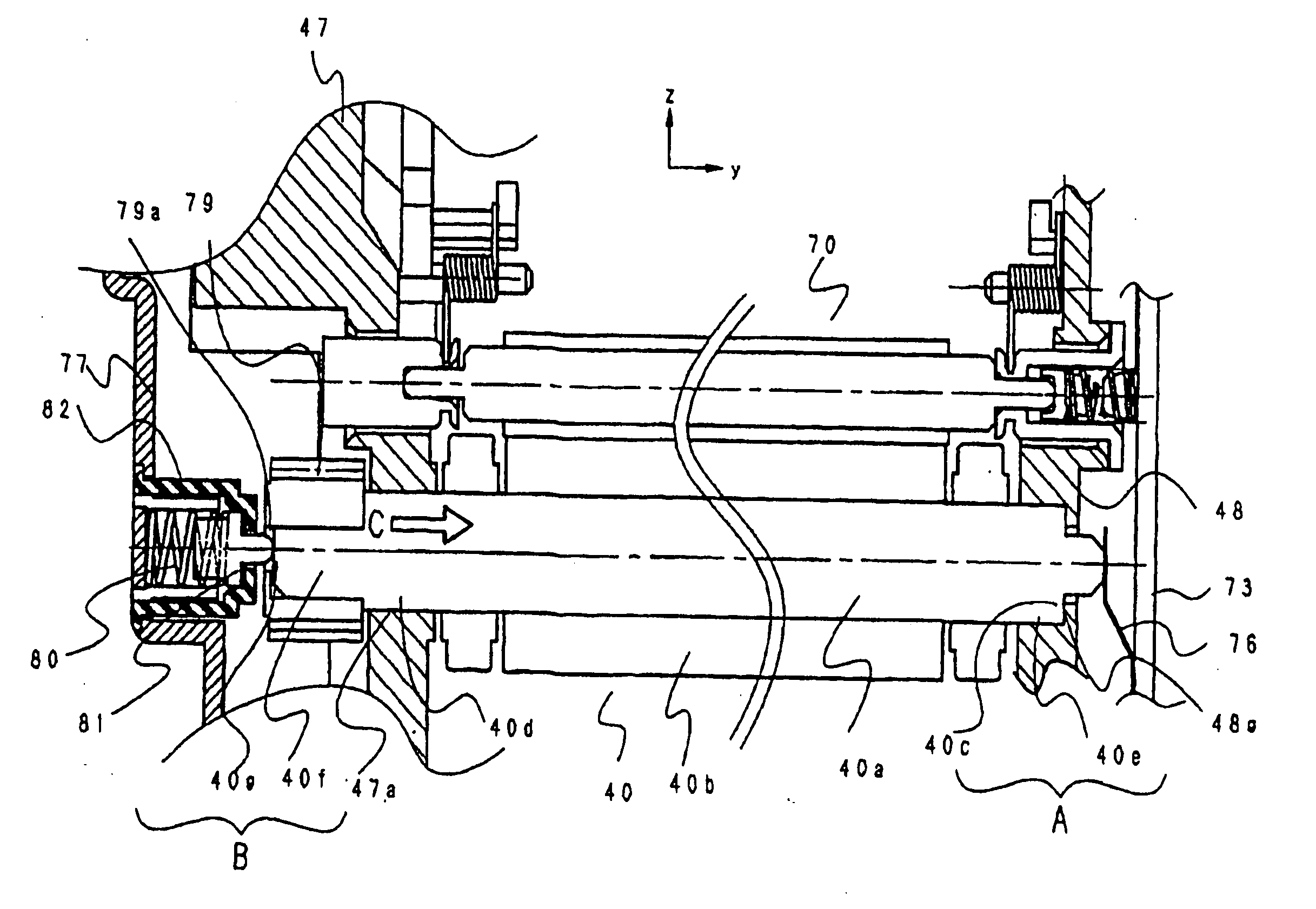
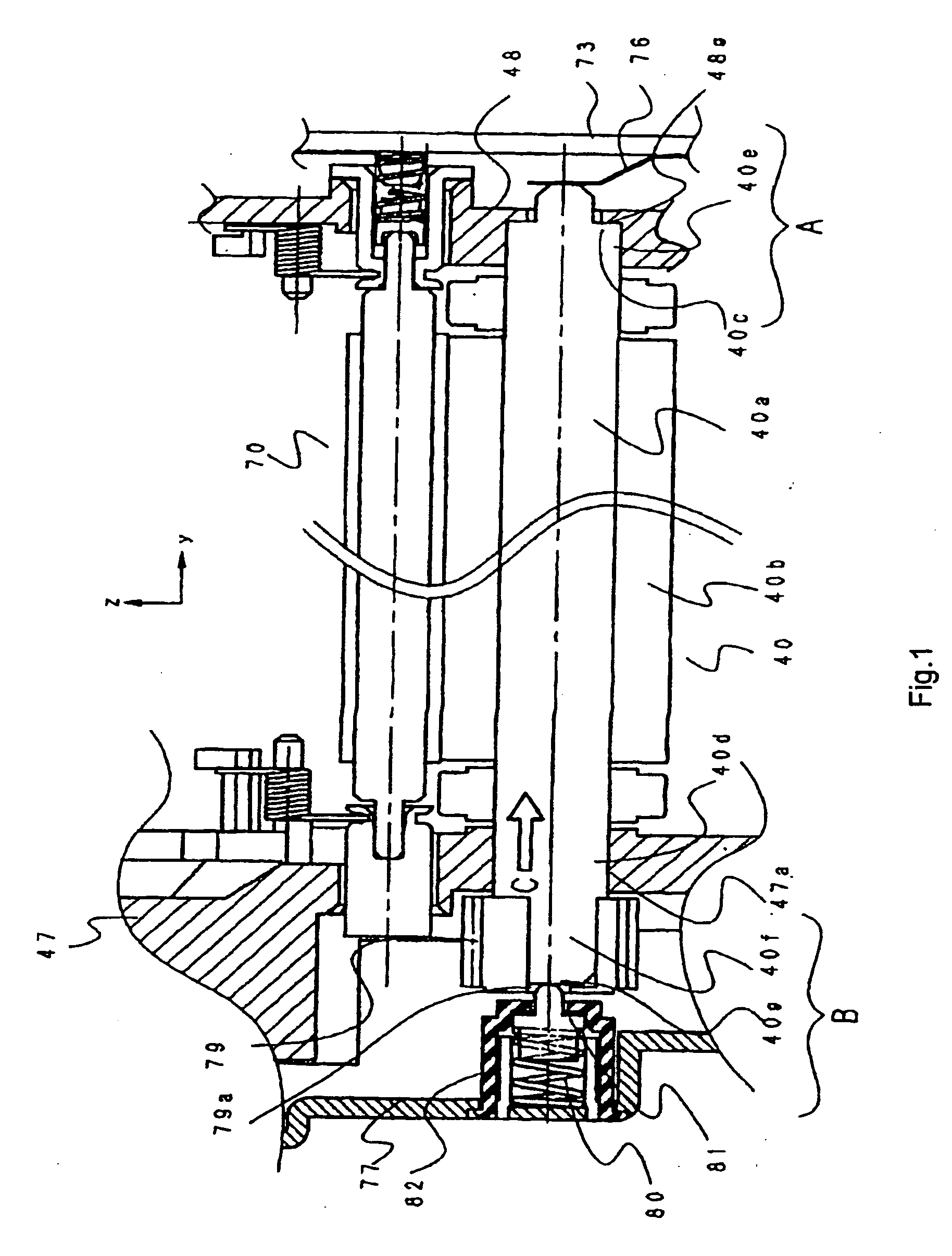
[0016] It is an object of the present invention to provide a developing device, a developing cartridge, a process cartridge, and an image forming apparatus in which the position of the developing roller in the thrust direction can remain constant.
[0018] Still another object of the present invention is to provide a developing device, a developing cartridge, a process cartridge, and an image forming apparatus in which the position of the developing roller in the thrust direction can remain constant not only during image formation, but also during the attachment of a developing device, a developing cartridge, and a process cartridge to the image formation apparatus.

Problems solved by technology

Here, it is to be expected that during its transportation, the process cartridge suffers from vibrations in various directions.
However, the contact pressure immediately after the application of the driving force to the developing roller 240 is not fixed.

Method used


Image

  • Developing device, developing cartridge, process cartridge, and image forming apparatus using these
  • Developing device, developing cartridge, process cartridge, and image forming apparatus using these
  • Developing device, developing cartridge, process cartridge, and image forming apparatus using these

Examples


first embodiment

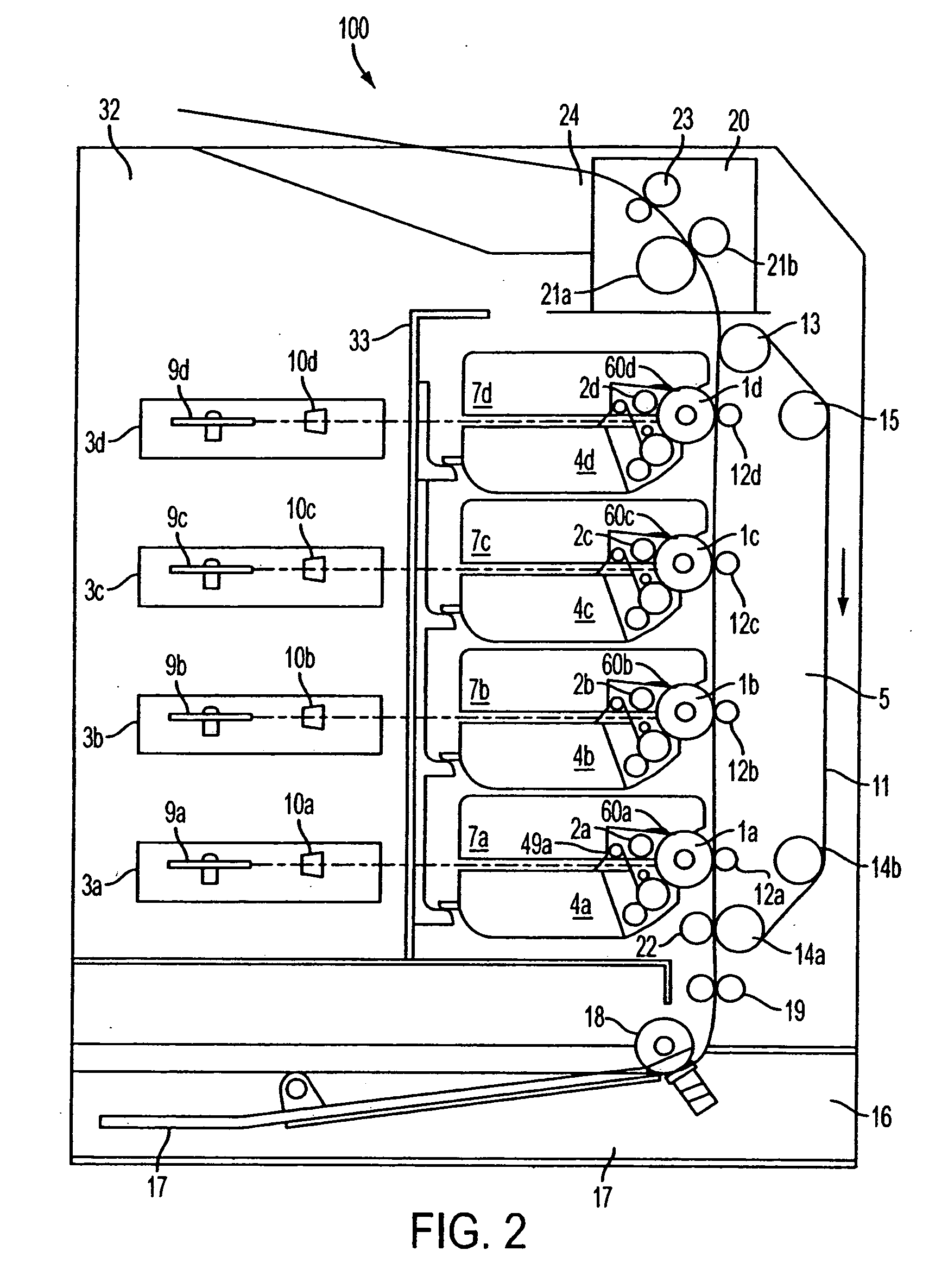
[0089] A developing device, a developing cartridge, a process cartridge, and an image forming apparatus according to a first embodiment of the present invention will be described with reference to FIGS. 1 through 11.

(General Construction of the Image Forming Apparatus)

[0090] First, the general construction of the image forming apparatus will be schematically described with reference to FIG. 2. The image forming apparatus 100 shown in FIG. 2 is equipped with four photosensitive drums 1a through 1d serving as the image bearing members arranged side by side in the vertical direction. The photosensitive drums 1a through 1d are rotated counterclockwise as seen in the drawing by a driving means (not shown).

[0091] Respectively arranged around the photosensitive drums 1a through 1d, successively in the rotating direction thereof, are charging devices 2a through 2d for uniformly charging the surfaces of the photosensitive drums 1a through 1d, scanner units 3a through 3d adapted to apply ...

second embodiment

[0147]FIGS. 12 through 14 show a second embodiment of the present invention. The general construction of the image forming apparatus is the same as that of the first embodiment described above. The following description will focus on the features of the second embodiment, and a description of the components which are the same as those of the first embodiment will be omitted as appropriate.

(Construction of the Process Cartridge)

[0148] The general construction of the cleaning unit and the developing unit is the same as that of the first embodiment.

(Details on the Urging Means)

[0149]FIGS. 12 through 14 show the urging means of this embodiment in detail. The constructions of the developing roller 40 and the retaining members 47 and 48 are the same as those of the first embodiment.

[0150] As shown in FIGS. 12 through 14, the side cover 77 is equipped with a cylindrical portion 77d for mounting the pressurizing spring 80 and the sliding member 81 from the outside with respect to the...

third embodiment

[0159]FIGS. 15 and 16 show a third embodiment of the present invention. The general construction of the image forming apparatus is the same as that of the first embodiment described above. The following description will focus on the features of the third embodiment, and a description of the components which are the same as those of the first embodiment will be omitted as appropriate.

(Construction of the Process Cartridge)

[0160] The general construction of the cleaning unit and the developing unit is the same as that of the first embodiment.

(Details on the Urging Means)

[0161]FIGS. 15 and 16 show the urging means of this embodiment in detail. The constructions of the developing roller 40 and the retaining member 47 are the same as those of the first embodiment.

[0162] As shown in FIGS. 15 and 16, the side cover77 is equipped with a retaining portion 77e for retaining the sliding member 81. Around the retaining portion 77e, there is provided a guide wall 77f having a diameter lar...


PUM


Abstract

Disclosed are a developing device, a developing cartridge, a process cartridge, and an image forming apparatus in which image deficiency is prevented by absorbing the tolerance of each component and making the position of the developing roller in the thrust direction constant and which are easy to assemble. A frame member is equipped with an urging unit that axially urges the developing roller, the urging unit urging the developing roller in the direction of movement of the developing roller by the thrust force of a helical gear when a driving force is transmitted to the developing roller, to thereby make the position of the developing roller in the thrust direction constant.

Description

CROSS REFERENCE TO RELATED APPLICATION [0001] This application is a divisional application of application Ser. No. 10 / 403,282, filed Apr. 1, 2003, pending.[0002] This application claims the right of priority under 35 U.S.C. § 119 based on Japanese Patent Application No. JP 2002-161808 which is hereby incorporated by reference herein in its entirety as if fully set forth herein. BACKGROUND OF THE INVENTION [0003] 1. Field of the Invention [0004] The present invention relates to a developing device, a developing cartridge, a process cartridge, and an image forming apparatus using these, which are applicable to an electrophotographic copying machine, printer or the like. [0005] 2. Description of the Related Art [0006] Conventionally, an image forming apparatus using the electrophotographic image forming process adopts a process cartridge system, in which the image bearing member and the process means acting thereon are integrated into a cartridge, which is detachable with respect to th...

Claims


Application Information

Patent Timeline
IPC IPC(8): G03G15/06G03G21/18G03G15/08
CPCG03G2215/0634G03G15/0896
Inventor NITTANI, SUSUMUYOKOMORI, KANJITSUDUKI, MASATOMO
Owner CANON KK
Learn More