Low-flow valve

a low-flow, valve technology, applied in the field of valves, can solve the problems of plant death, plant damage, plant roots being damaged, etc., and achieve the effect of reducing the number of valves

Active Publication Date: 2006-01-26
RAIN BIRD CORP
View PDF19 Cites 34 Cited by
  • Summary
  • Abstract
  • Description
  • Claims
  • Application Information

AI Technical Summary

Problems solved by technology

However, plants that have low water consumption needs typically do not respond well to over-watering.
If the plants become soaked for long periods of time, the plants can die or their roots may suffer damage, such as root-rot.
Furthermore, such plants often survive in loose soil or soil with a significant amount of sand, which contributes to the soil's inability to absorb excess water.
This type of soil can become over-saturated easily, and the plants may not be able to remain in the loosened soil.
For at least these reasons, unreliable controls and the valves for these irrigation systems can be expensive to crops.
However, some dirt can become lodged between the cylindrical port and the dome when the dome attempts to move from the open position to the close, thereby trapping the dirt between the cylindrical port and the dome.
This size frequently can be larger than the gap between the dome and the cylindrical port of the opened low-flow valve, and can become lodged against or within the gap.
In the event dirt or other foreign material becomes trapped between the dome and the cylindrical port, the valve may not close sufficiently and will allow an undesirable amount of water to still pass through the valve.
The material may become lodged when the valve is open and the dome is positioned away from the cylindrical port, or it may become caught when the dome moves towards and against the cylindrical port as the valve is being closed.
In such an event, an undesirable amount of water may continue to pass through the valve.
This may result in an unnecessary use of water or in over-irrigation of the soil and plants, as well as other undesirable results.
In a typical valve of this kind, closing the valve can be violent and provide shock to the flow system and valve.
For instance, the dramatic drop in flow can cause rapid changes in pressure along the system.
This causes a high amount of friction between the water and the dome or diaphragm, causing the diaphragm to be pulled towards the cylindrical port or diaphragm seat.

Method used


Image

  • Low-flow valve
  • Low-flow valve
  • Low-flow valve

Examples


second embodiment

[0044] the insert, referenced herein as insert 250, is depicted in FIGS. 8-10 in cooperation with the diaphragm 40. The insert 250 has an interrupted radial periphery 253 such that a top side 252 has small notches 254 extending radially outward and on an outside circumferential surface 256. As can be seen, the rib 94 of the diaphragm 40 is positioned near the radial periphery 253 of the top side of the insert 250. Together, the rib 94 and the top side notches 254 define openings 260 for permitting water and small particulate matter to pass therethrough, while prohibiting relatively large particulate matter from passing. Again, the insert 250 has an annular ridge 262 that forms a seal with the dome 90, as described for insert 50 and as shown in FIG. 8.

[0045]FIG. 9 shows the insert 250 and diaphragm 40 in an arrangement similar to that of FIG. 6. The dome 90 is actuated to move a short distance away from the ridge 262 to permit passage of water and particulate matter that is able to p...

third embodiment

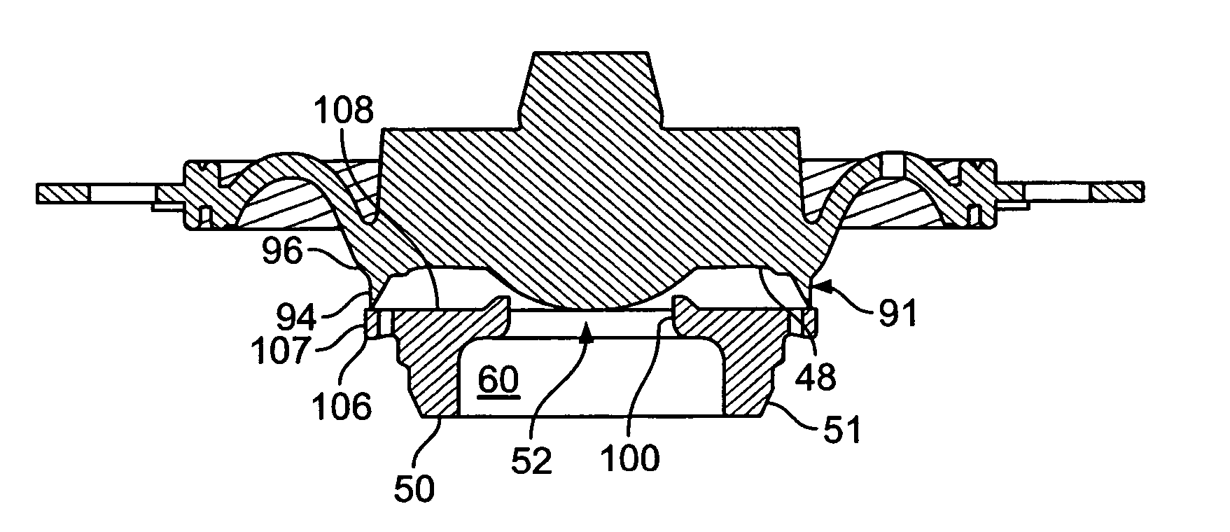
[0048]FIGS. 11 and 12 depict the insert, referenced as insert 350, and the diaphragm 40. The insert 350 has a top side 352 with a continuous, uninterrupted surface. As depicted in FIG. 11, a closed position is depicted wherein the annular rib 94 of the diaphragm 40 is in contact with the top side 352, and wherein the dome 90 is in contact with a ridge 362 on the insert 350.

[0049] With this embodiment of the insert 350, any foreign particulate matter that may become trapped between the rib 94 and the insert 350, or between the dome 90 and the ridge 362, does not completely or necessarily violate the integrity of the seal between the diaphragm 40 and the insert 350. More specifically, the contact between the dome 90 and the ridge 362 and the contact between the rib 94 and the insert 350 combine to form a seal that seals completely or enough such that an undesirable amount of water does not pass through the valve.

[0050]FIG. 12 depicts the diaphragm 40 and the insert 350 in an open pos...


PUM


Abstract

A low-flow diaphragm valve is disclosed having a flexible diaphragm that cooperates with a portion of the valve body to open and close the valve. The diaphragm may have a dome for seating in a passage between the inlet and outlet of the valve, and the passage may be surrounded by an annular ridge for contacting the dome. The diaphragm may have one or more ribs for seating against other portions of the body located around the passage. The valve body may include openings or interruptions to permit fluid to flow through the valve, as well as to permit relatively small particulate matter to flow through. The diaphragm may have a first open position and/or a second open position such that the ribs and openings may perform screening functions to block or restrict particulate matter of relatively large size from flowing to the passage between the dome and the valve body. The ribs and the openings or interruptions may cooperate to perform the blocking function and to prevent an undesirable amount of liquid from passing through the valve even when particulate matter is trapped between one or more of the dome and ribs, on the one hand, and the body on the other hand.

Description

FIELD OF THE INVENTION [0001] The invention relates to a valve and, in particular, to a low-flow valve with improved sealing characteristics. BACKGROUND OF THE INVENTION [0002] Currently, low-flow fluid systems are utilized for controlled irrigation of crops, vegetation, landscaping, and the like. Commonly, these flow systems utilize a fluid or water source, a pumping system in communication with the water source, a network of fluid delivery conduits or pipes, a plurality of end point emitters for fluid dispersement, one or more control valves for opening or closing the fluid delivery conduits to turn on or off the emitters, and a number of controllers for actuating the valves. The emitters provide a slow drip or trickle flow. Furthermore, each valve may be paired with a debris trap for collecting particulate matter that cannot escape through the emitter itself. A representative low-flow system may include 10-15 valves on a single controller, and each valve may communicate with 20-1...

Claims


Application Information

Patent Timeline
Patent Type & Authority Applications(United States)
IPC IPC(8): F16K11/04
CPCF16K31/365F16K7/17Y10T137/86702Y10T137/86718
Inventor IRWIN, KEVIN M.ROPER, PHILIP G.SALVIANO, MATTHEW M.THOMPSON, JOHN E.HAAS, CLINTOLIVAS, VICTOR
Owner RAIN BIRD CORP
Why Eureka
Try Eureka