

Repulsive differential driving double-acting type electrical machinery power system
a technology of double-acting and differential transmission, which is applied in the direction of motor deposition, vehicle components, propulsion parts, etc., can solve the problems of large weight, high cost of additionally installed differential transmission devices, and existence of normal transmission loss
- Summary
- Abstract
- Description
- Claims
- Application Information
AI Technical Summary
Benefits of technology
Problems solved by technology
Method used
Image

Examples
Embodiment Construction
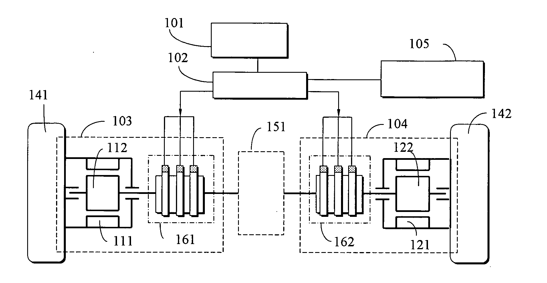
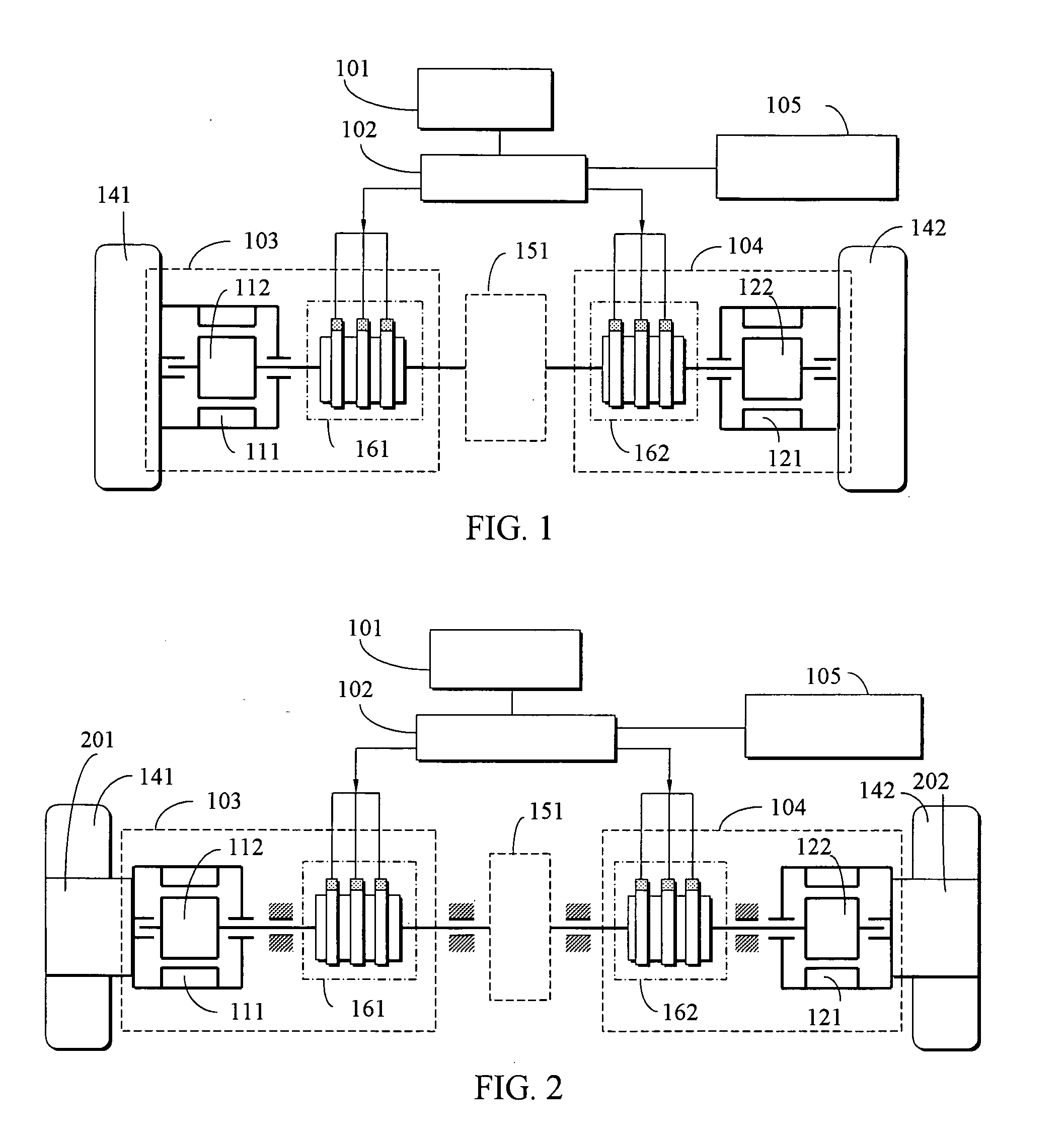
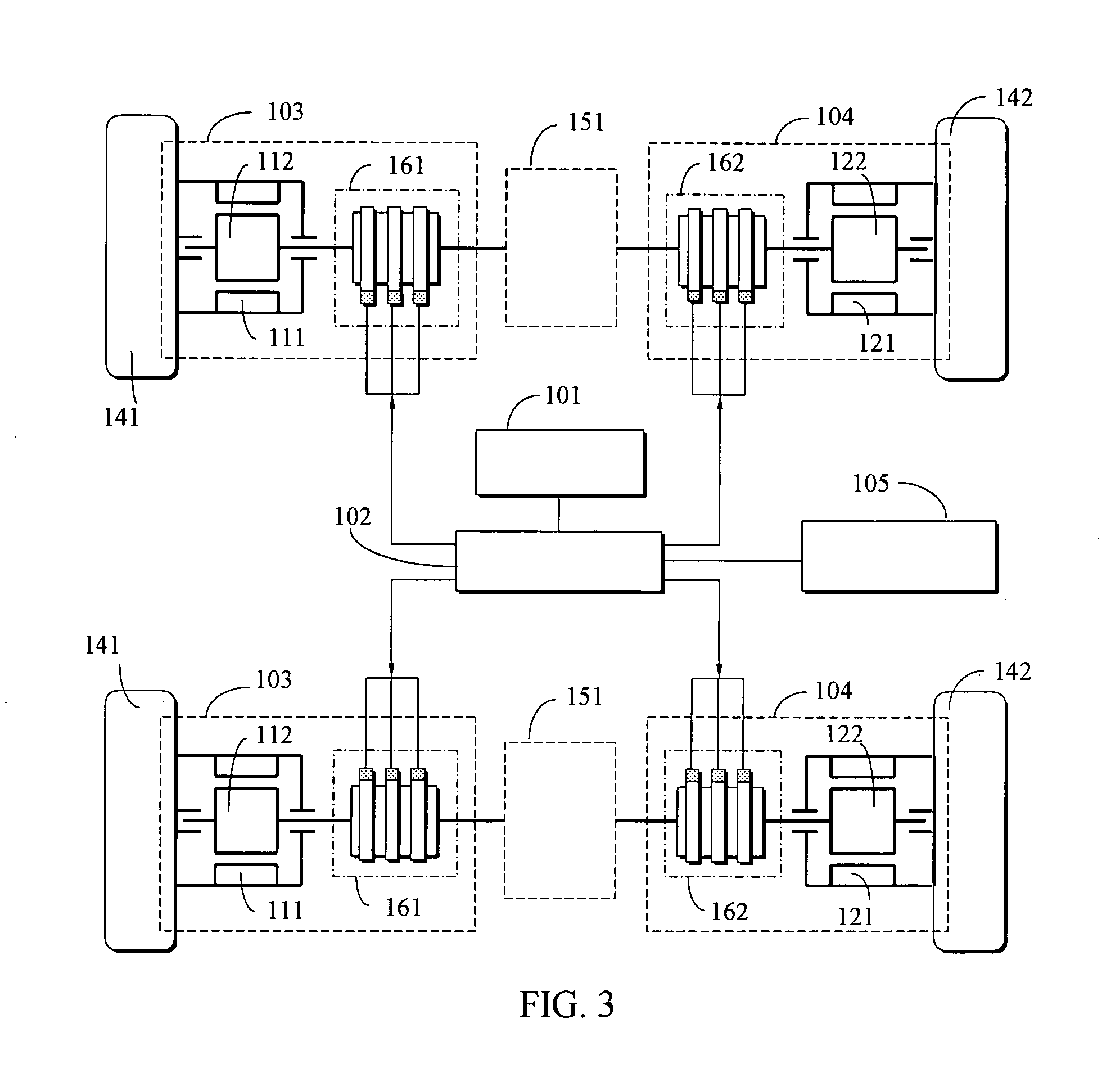
[0016] According to the invention, the repulsive differential driving double-acting type electrical machinery power system is comprised of twin double-acting type electrical machinery assembly each having a first interactive rotational electrical machinery assembly structure and a second interactive rotational electrical machinery assembly structure, and the double-acting type electrical machinery assembly is constituted by the AC or DC, brush-less or brushed, synchronous or asynchronous, cylindrical shaped or disk shaped cup shaped electrical machinery assembly, whereof its constituting methods includes: one interactive rotational electrical machinery assembly structure is coupled with the load while the other interactive rotational electrical machinery assembly structure is coupled with a differential unit to allow each aforesaid double-acting type electrical machinery assembly appear in back to back coupling with the differential device in any axial directions, and in case that a...
PUM
 Abstract
Description
Claims
Application Information