Elevator roping arrangement

a technology for elevators and roping, which is applied in the direction of elevators, mine lifts, transportation and packaging, etc. it can solve the problems of not employing machine rooms, elevator car and counterweight must be suspended within the hoistway in a different way, and small machines employed in mrl applications tend to require small sheave diameters for the driv

Inactive Publication Date: 2006-01-26
INVENTIO AG
View PDF12 Cites 46 Cited by
  • Summary
  • Abstract
  • Description
  • Claims
  • Application Information

AI Technical Summary

Benefits of technology

[0009] The elevator assembly according to an embodiment of the present invention advantageously permits the location of a counterweight in a rear configuration for an MRL elevator installation without less limitations on the type of roping employed. Moreover, this elevator assembly provides this configuration while assuring a balanced loading of the elevator car.
[0010] The elevator assembly according to an embodiment of the present invention also provides for a deflector sheave located relative to the drive sheave so that the ropes wrap around the drive sheave greater than 180 degrees, thus assuring the desired tractive capabilities.
[0011] The elevator assembly according to an embodiment of the present invention also provides for an underslung sheave assembly that allows for full, balanced support of the elevator car while allowing the ropes to extend from the underslung sheave assembly to a single deflector sheave and a single drive sheave.

Problems solved by technology

As this name implies, this type of elevator mechanical system does not employ machine rooms at all.
As these MRL elevator installations become more common, a problem that arises with them, however, is that the elevator car and counterweight must be suspended within the hoistway in a different manner than in prior art elevator installations having machine rooms.
However, the small machines employed in MRL applications tend to require small sheave diameters for the drive sheaves.
But a side mounted counter weight configuration creates hoistway packaging issues in certain standard sized hoistways that are designed for front opening elevators with rear located counter weights.
These bends in conventional steel suspension ropes may not be particularly desirable.
Thus, these configurations may limit the choice of the type of roping employed in the elevator installation.

Method used


Image

  • Elevator roping arrangement
  • Elevator roping arrangement
  • Elevator roping arrangement

Examples


Embodiment Construction

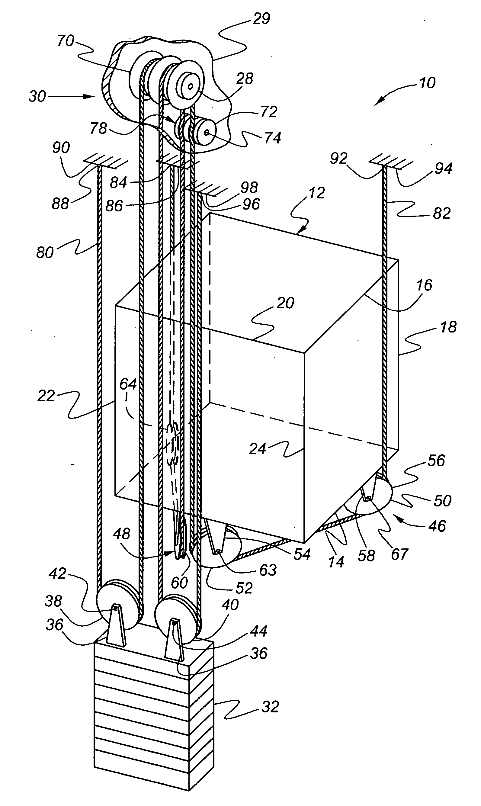
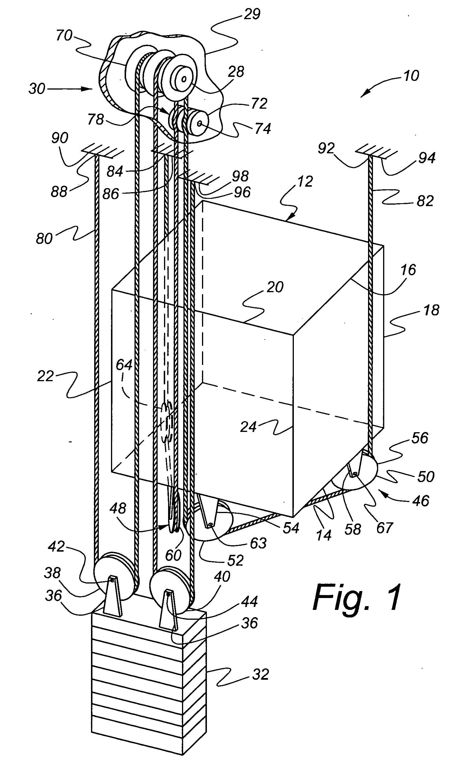
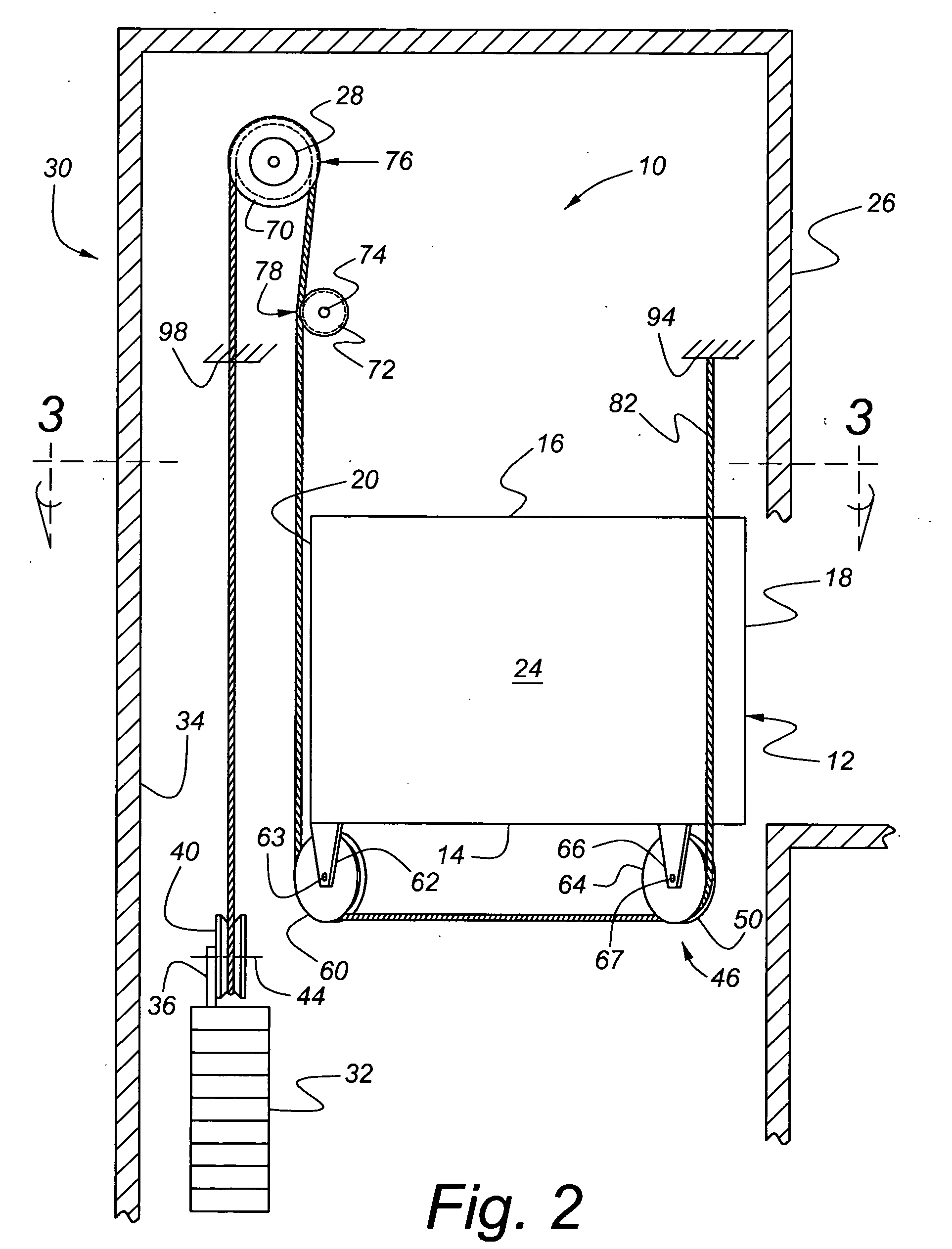
[0016] Referring now to FIGS. 1-3, an elevator installation in accordance with the present invention is indicated generally at 10. This elevator installation is an MRL configuration, with the elevator components mounted in an elevator hoistway 26, rather than providing a machine room located outside of the hoistway 26. The elevator installation includes an elevator car 12, which includes a floor 14, a roof 16, a front 18, a rear wall 20, a first side wall 22 and a second side wall 24. The elevator car 12 is disposed in the elevator hoistway 26 and is operable to move along a conventional vertical elevator travel path. The elevator car 12 is mounted to slide along and be guided by elevator guide rails (not shown) in a conventional fashion.

[0017] The elevator car 12 is supported by an underslung sheave assembly 46, which includes a first underslung sheave subassembly 48 and a second underslung sheave subassembly 50. The first underslung sheave subassembly 48 has a first underslung sh...


PUM


Abstract

An elevator installation includes an elevator car located in a hoistway and having a floor, and a rear wall extending upward from the floor. A counterweight is located in the hoistway adjacent to the rear wall of the elevator car. An underslung sheave assembly is located generally below the floor and preferably forms a V-shaped configuration that operatively engages the elevator car. A drive machine is mounted in the upper portion of the hoistway, and a drive sheave operatively engages the drive machine and is located above the counterweight, with the drive sheave having a front edge. A deflector sheave is also mounted in the upper part of the hoistway generally below the drive sheave and has a rear edge that vertically overlaps with the front edge of the drive sheave. A first rope and a second rope each have a first end attached to one of a first and a second dead end hitch in the upper portion of the hoistway, with the underslung sheave assembly operatively engaging the first and second ropes to support the elevator car and the counterweight operatively engaging the first and second ropes as the first and second ropes extend from the drive sheave to the counterweight, and with the first and second ropes extending from the underslung sheave assembly around the rear edge of the deflector sheave and the front edge of the drive sheave such that the first and second ropes wrap around the drive sheave greater than 180 degrees.

Description

BACKGROUND OF THE INVENTION [0001] The present invention relates generally to roping configurations for elevators. [0002] Elevators and their associated mechanical components are well known. Elevators are used to move people and equipment between floors in multistory buildings. A conventional traction type elevator installation includes an elevator car mounted in a car frame and moveable in a hoistway, a counterweight attached to the car via a rope, and a machine driving a traction or drive sheave that is engaged with the rope. As the machine turns the drive sheave, friction forces between the surface of the sheave and the rope move the rope and thereby cause the car and counterweight to raise and lower in opposite directions. The rope also can be routed through various turning or diverting sheaves when the drive sheave is not positioned directly above the car and the counterweight. [0003] The mechanical components of the conventional elevator drive are generally located in a machin...

Claims


Application Information

Patent Timeline
Patent Type & Authority Applications(United States)
IPC IPC(8): B66B9/02B66B7/06B66B11/00
CPCB66B11/008
Inventor KOEPPE, ROBERT J. JR.
Owner INVENTIO AG
Why Eureka
Try Eureka