Bicycle disc brake rotor

a disc brake and rotor technology, applied in the direction of cycle brakes, braking elements, cycle equipment, etc., can solve the problems of reducing weight, and achieve the effects of preserving overall thinness, preserving strength, and reducing wear resistan

Inactive Publication Date: 2006-01-26
SHIMANO INC
View PDF10 Cites 4 Cited by
  • Summary
  • Abstract
  • Description
  • Claims
  • Application Information

AI Technical Summary

Benefits of technology

[0011] Another object of the present invention is to provide a bicycle disc brake rotor that uses two members of different types of materials tightened to a hub or a hub mounting member, which reduces and / or eliminates compression / deformation of the different materials.
[0041] A depression is formed around the fixing hole in the present invention, so that when the depression is formed, for example, by compressing the first readily deformable first member by means of a stepped pressing process while the second member is mounted on both sides of the first member, or a component serving as a preliminary depression of the first member is formed by being cut into a cylindrical shape through a machining process, for example, and one of the second members is aligned with it to form a concave shape by means of a pressing process or the like, the first member will be less likely to be further compressed, with less likelihood of becoming dented. The rotor member can thus be effectively tightened by the fixing means when fixed to the hub or mounting member, without any tightening problems.

Problems solved by technology

Particularly in the case of bicycles, which run on the use of human power, reducing the weight is one of the most important issues.

Method used


Image

  • Bicycle disc brake rotor
  • Bicycle disc brake rotor
  • Bicycle disc brake rotor

Examples


Embodiment Construction

[0055] Selected embodiments of the present invention will now be explained with reference to the drawings. It will be apparent to those skilled in the art from this disclosure that the following descriptions of the embodiments of the present invention are provided for illustration only and not for the purpose of limiting the invention as defined by the appended claims and their equivalents.

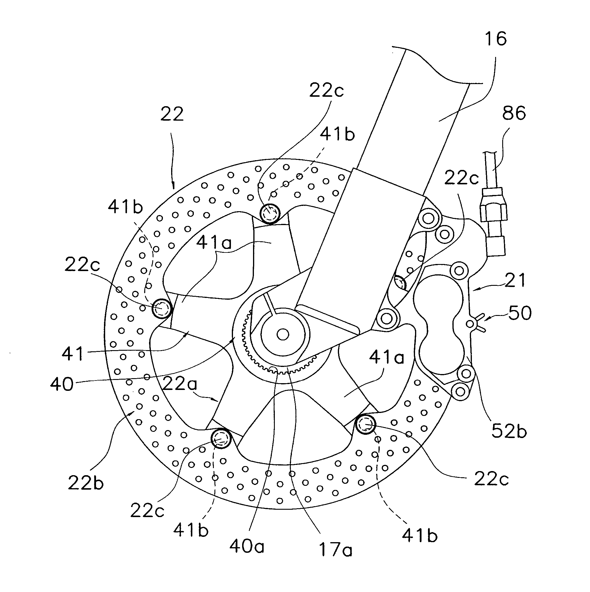
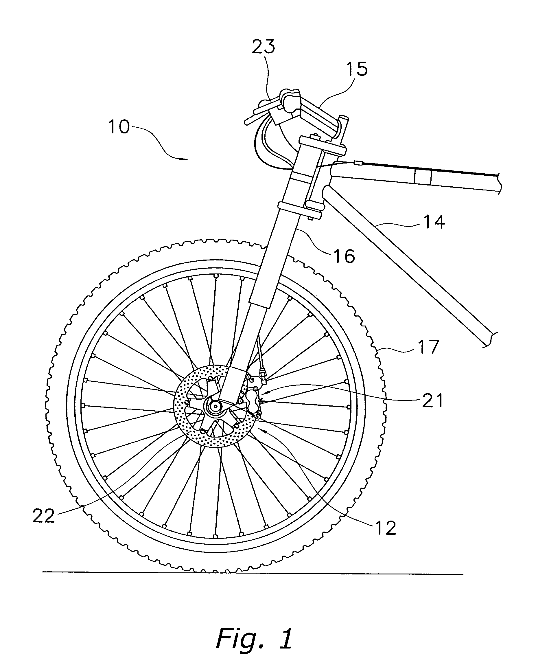
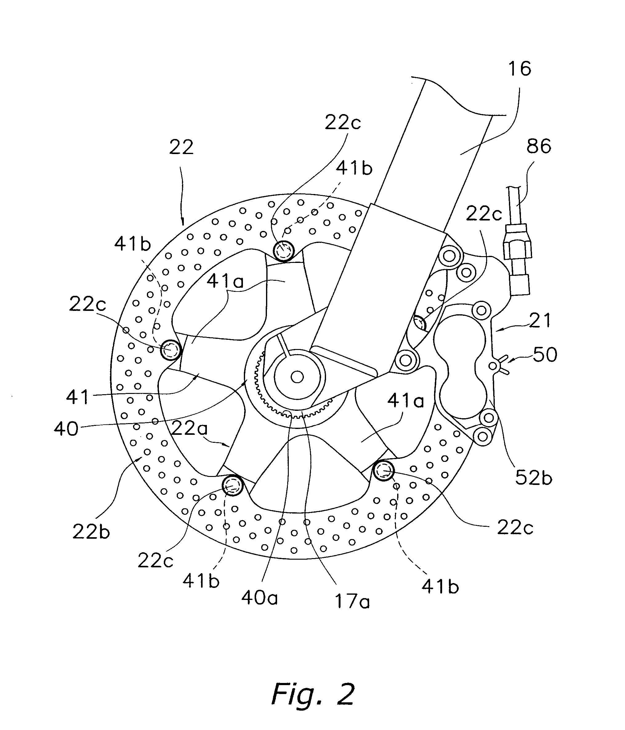
[0056] Referring initially to FIG. 1, a bicycle 10 is illustrated with a bicycle disc brake device 12 mounted thereon in accordance with a preferred embodiment of the present invention. The various parts and / or components (technology) of bicycles such as the bicycle 10 are generally well known in the bicycle art. Accordingly, the bicycle 10 and the various structural and operating components of the bicycle 10 will not be described and / or illustrated in detail herein, except as related to the bicycle disc brake device 12 of the present invention.

[0057] The bicycle 10 is conventionally known, exce...


PUM


Abstract

A composite material bicycle disc brake rotor is provided for a bicycle disc brake device and is designed to be mounted to a bicycle wheel hub directly or using a hub mounting member. The rotor basically includes a rotor member and a fastening member. The rotor member has a first ring-shaped member and a pair of second ring-shaped members disposed on opposite sides of the first member. The second members include a material with higher wear resistance than the first member. At least one fixing hole is formed through the first and second members and a depression is formed around the fixing hole on the surface of one of the second members. The fastening or tightening member is mounted through the fixing hole of the rotor member to fix the rotor member to another member.

Description

CROSS-REFERENCE TO RELATED APPLICATIONS [0001] This application claims priority to Japanese Patent Application No. 2004-213148. The entire disclosure of Japanese Patent Application No. 2004-213148 is hereby incorporated herein by reference. BACKGROUND OF THE INVENTION [0002] 1. Field of the Invention [0003] The present invention generally relates to a disc brake rotor, which selectively contacts the brake pads of a bicycle disc brake caliper. More specifically, the present invention relates to a composite material bicycle disc brake rotor designed to be mounted to a bicycle wheel hub without deformation of the rotor during attachment. [0004] 2. Background Information [0005] Bicycling is becoming an increasingly more popular form of recreation as well as a means of transportation. Moreover, bicycling has become a very popular competitive sport for both amateurs and professionals. Whether the bicycle is used for recreation, transportation or competition, the bicycle industry is consta...

Claims


Application Information

Patent Timeline
Patent Type & Authority Applications(United States)
IPC IPC(8): B62L1/00
CPCB62L1/005F16D65/12F16D2065/1316F16D2200/0052F16D2200/003F16D2200/0039F16D2065/132
Inventor TAKIZAWA, SHINICHI
Owner SHIMANO INC
Why Eureka
Try Eureka