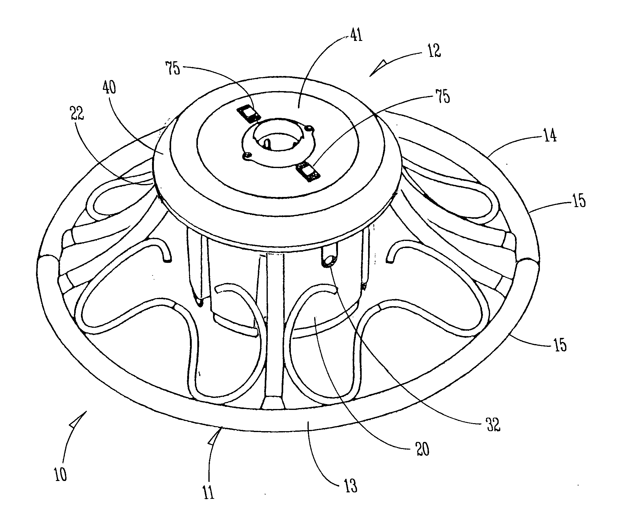
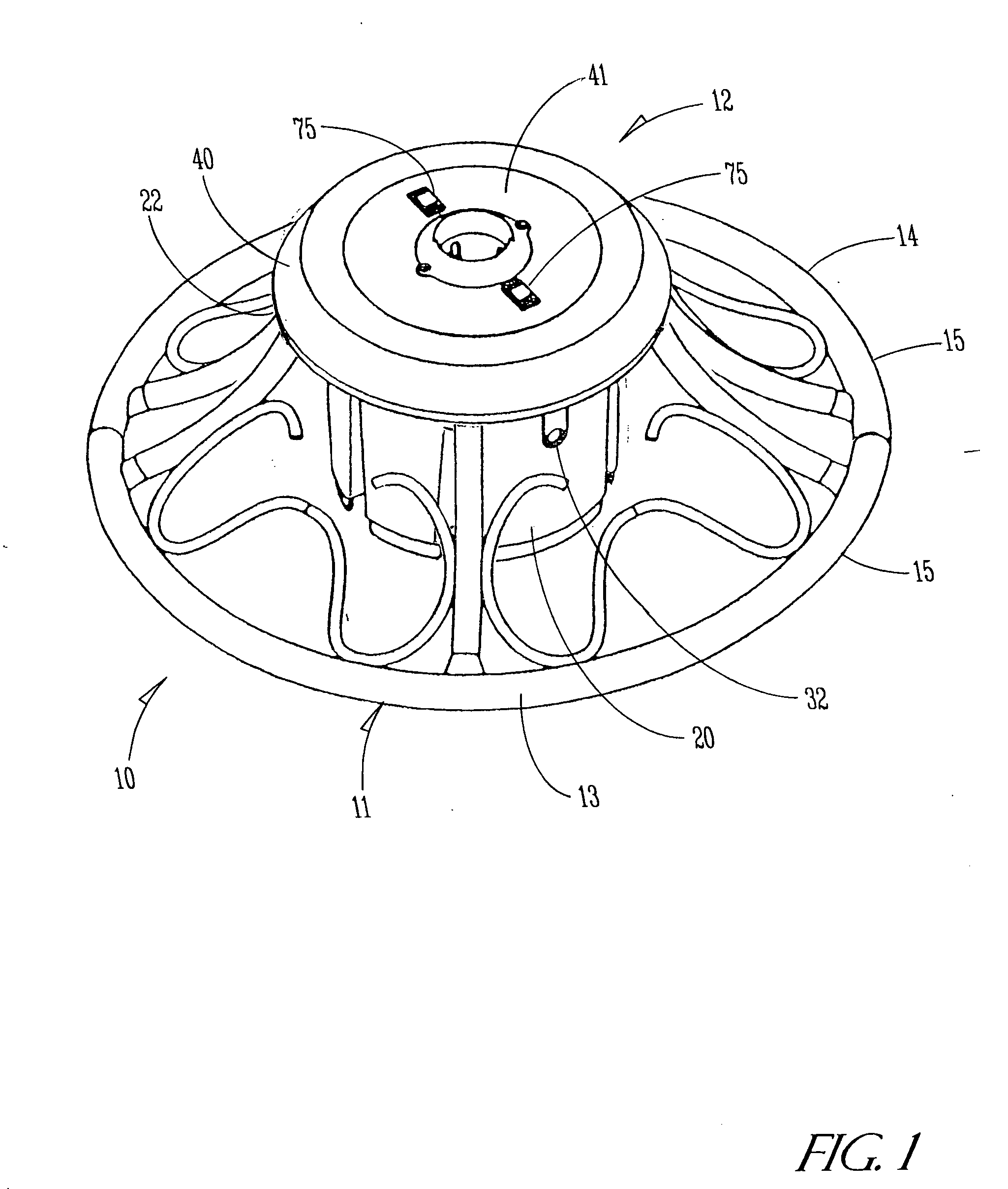
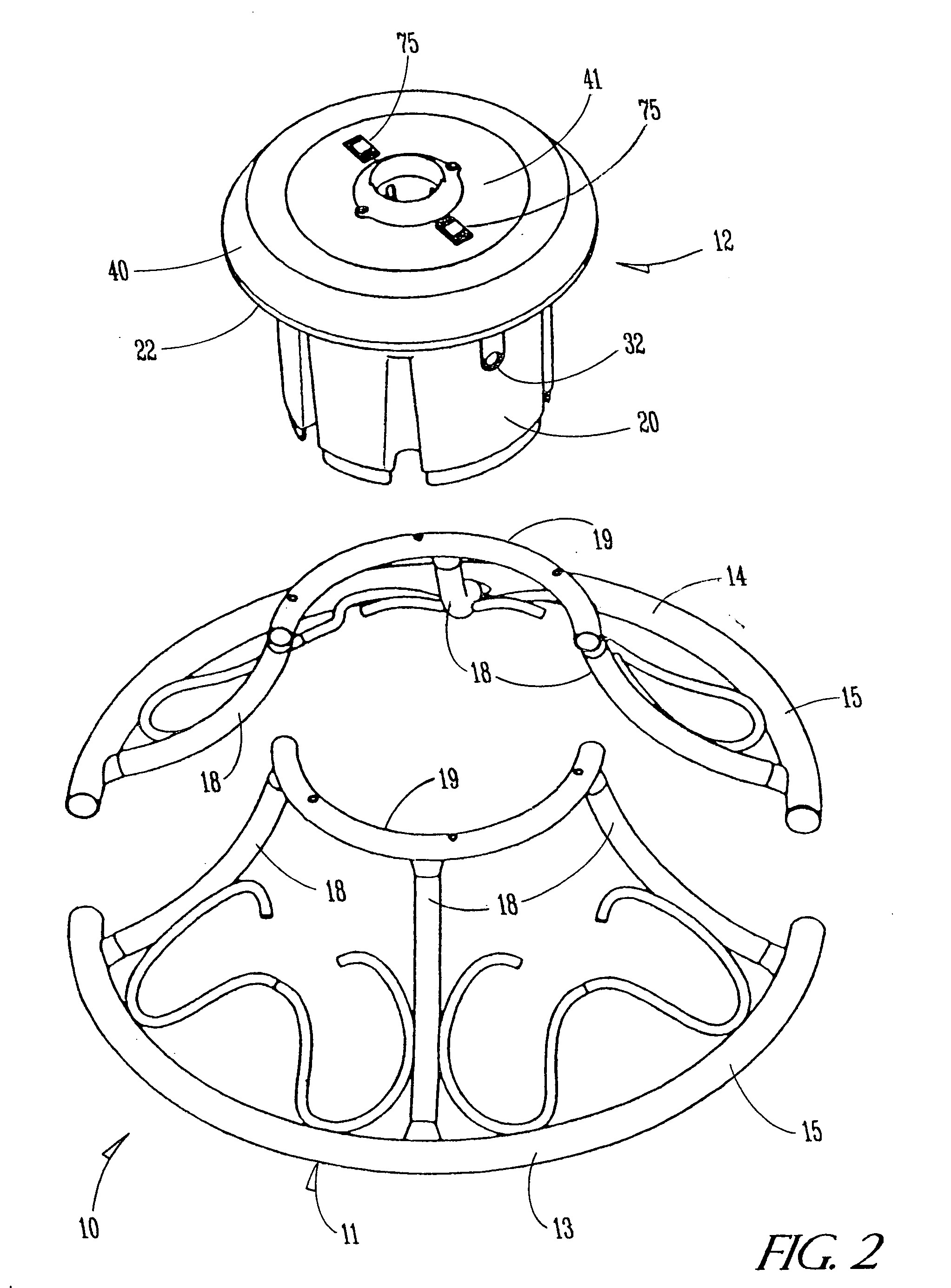
[0020] Referring now to the drawings and with reference first to FIGS. 1 and 2, a preferred embodiment of an improved revolving support stand of the present invention is shown generally at 10 and is adapted preferably for supporting the trunk of a decorative display such as a Christmas tree (not shown). The support stand 10 includes a support base 11 and a rotational unit 12 that is elevated in an off-the-ground position by the base 11.
[0021] Preferably the base 11 is divided into two equal mirror image sections 13 and 14 that each include curved, rod shaped feet 15 that provide, when located adjacent to one another, a substantially circular bottom ring 16 for engaging the surface upon which the stand 10 is supported, such as the floor of a building. Extending upwardly in each section 13 and 14 are preferably three arcuately shaped side members 18 that terminate in top ring portions 19 that are designed to engage and support the rotational unit 12 as will be described in further detail below.
[0022] Referring now to FIG. 3, the rotational unit 12 comprises an outer casing 20 with an open top 21 and a turntable assembly 22 that is adapted to be seated in said casing 20 and is secured thereto by screws, not shown. The casing 20 is formed in somewhat of a cylindrical basket shape and is ornamentally designed with vertically aligned recesses 26 about its sidewall 27, which recesses 26 also serve as a means for providing abutments 28 on the interior of the casing in 20 and which have screw holes 29 through which screws, not shown, can be disposed to serve as a retaining means between the casing 20 and the turntable assembly 22.
[0023] At the top of the casing sidewall 27 is an outwardly extending arcuately shaped flange 30 that circles entirely around the top of the casing 20 and is sized to receive the top ring portions 19 of the base sections 13 and 14 to essentially join the top portions of such sections together. Spaced equally apart on the upper surface of the flange 30 are a plurality of protruding spacers 31 designed to provide a small amount of spacing between the flange 30 and the turntable assembly 22 when they are assembled together. The casing sidewall 27 further includes an opening 32 for the passage therethrough of an electrical cable 33 that provides electrical power to the stand 10. The electrical cable 33 includes a power on/off switch 34 and a male plug 35 for insertion into an electrical outlet of a building.
[0024] Referring now to FIGS. 3, 4, 5 and 6, the turntable assembly 22 includes a shell housing 40 and a rotatable platform 41 that is seated in the shell housing 40. As shown best in FIG. 3, the shell housing 40 has an upper portion 42 that is generally circular in configuration and conforms in size to the top of the casing 20. A centrally disposed hollow sleeve 43 extends downwardly from the upper shell housing portion 42. A circularly shaped recess 44 is formed in the top of the shell housing 40, which recess has a floor 45 with a circularly shaped opening 46 that opens to the hollow sleeve 43. The sleeve 43 has its largest diameter at the opening 46 as the sleeve 43 is reduced in size to provide an interior ledge 47 spaced a relatively short distance from the floor 45. The ledge 45 is located to serve as a seat for a large bearing race 48 in which a plurality of steel balls are set to serve as a trust bearing to overcome the axial load applied on the platform 41 by the ornamental display supported by the stand 10.
[0025] The bottom end of the sleeve 43 is further reduced in size at 49 (see FIG. 5) to provide a second interior ledge that serves as a seat for a small bearing race 50 that is employed for a similar purpose to that provided by the race 48. Such reduced end 49 also serves as a hub on which a speed reduction gear 51 can be mounted in a rotatable relationship thereto as will be described in detail below.
[0026] The gear 51 is in meshing engagement with a drive gear 52 fixed on a drive shaft 53 of an electrical motor 54 mounted to two posts 55 on the shell housing 40 adjacent to the sleeve 43 as by screws or the like. The motor 54 is electrically connected to the power cord 33 so that when the switch 34 is actuated to an on condition, the motor 54 supplies rotational force to the gears 51 and 52. Extending upwardly from the motor 54 are electrical wires 60 for providing power to spring biased contacts 61 and 62 that are held in place on the shell housing floor 45 by a mount 63, as shown by FIGS. 7 and 8. The spring biased contacts 61 and 62 have electrically conductive terminals 64 that extend through openings in the floor 45 and are electrically connected to the wires 60.
[0027] Referring now to FIGS. 9 and 10, the rotatable platform 41 has a head 65 that is sized for being received in the recess 44 of the shell housing 40, and further includes a downwardly depending hollow shaft 66 that has an exterior generally conforming to the interior configuration of the sleeve 43 for reception therein. The exterior of the shaft 66 is stair stepped to provide an upper shoulder 67 that sits on the large bearing race 48 and a second shoulder 68 that engages and sits upon the small bearing race 50 so that the platform 41 is supported both near its top and bottom by the bearing races 48 and 50. By utilizing the two bearing races 48 and 50, the stand 10 is designed to accept heavier displays while at the same time maintaining smooth rotation.
[0028] The shaft 66 further includes a bottom end 69 that extends through the small race 50 for connection to the gear 51 in a fixed relationship by screws or the like. Consequently, rotation of the gear 51 causes rotation of the platform 41. Also, the gear 51 includes a pentagonally shaped node 76 that fits into a correspondingly shaped recess 77 (See FIG. 10) in the bottom of the end 69.
[0029] As best indicated in FIG. 10, the platform 41 has a bottom side 78 in which two circularly shaped recessed tracks 70 and 71 are formed to circle the shaft 66. The tracks 70 and 71 are sized to receive electrically conductive rings 72 and 73 that are fastened in place, as by screws, in their respective track. The conductive rings 72 and 73 are positioned so that when the platform 41 is inserted into the shell assembly 40, the ring 72 will engage the spring contact 61 and the ring 73 will engage the spring contact 62 to provide a means of transferring electrical power from the stationary contacts 61 and 62 to the rotating rings 72 and 73 of the platform 41.
[0030] Referring again to FIG. 9, two electrical outlets are provided in the platform 41 as will now be described. A pair of apertures 74 are formed in the platform head 65 for receiving female electrical receptacles 75 that extend through the head 65 and have spade terminals 76 electrically connected to the rings 72 and 73. Thus, the stand 10 provides a pair of electrical outlets in the head 65 for providing electrical power to the decorative display.
[0031] The rotatable platform head 65 has a round, central opening 80 that communicates with the hollow shaft 66 to provide an elongated bore for receiving the trunk of a decorative display. The bottom of the shaft 66 is closed to provide a support platform for the end of the trunk of the display. Preferably, the central opening 80 is sized to receive a tree stabilizing member 81 that is generally cylindrically shaped. The stabilizing member 81 has an inner ring 82 with fingers 83 that permit the trunk of the decorative display to be inserted therethrough in a tight frictional engagement to securely support the display in the stand 10. Preferably, the bottom end of the hollow shaft 66 also has a retaining means of some type positioned therein for engaging the bottom end of the display trunk and securing it therein. Although it is not critical to the present invention, to affix the stabilizing member 81 to the platform head 65, the member 81 preferably is secured to the head 65, as by screws at 84.
[0032] Thus, the present invention provides a durable and efficient support for displaying a decorative display in a rotational fashion that permits the use of electrical lights on the display. The foregoing description of the present invention is solely for illustrative purposes only. It is to be understood that the terminology that has been used is intended to be in the nature of words of description rather than of limitation. Many modifications and variations of the present invention are possible in light of the above teachings. For example, there are many different alternatives for providing the electrical circuitry necessary for the present invention and the particular circuitry disclosed is only one example of the type of the circuitry that could be utilized in the present invention. Therefore, the foregoing description is not to be taken as definitive of the scope of the invention; but rather that which is regarded as the invention as set forth in the following claims.