Driving method of active matrix display device
a display device and active matrix technology, applied in the direction of electric digital data processing, instruments, computing, etc., can solve the problems of increasing the drive voltage of the driver, power consumption, power consumption, etc., and achieve the effect of preventing the influence of liquid crystal alignment and preventing the influence of image alignmen
- Summary
- Abstract
- Description
- Claims
- Application Information
AI Technical Summary
Benefits of technology
Problems solved by technology
Method used
Image
Examples
embodiment 1
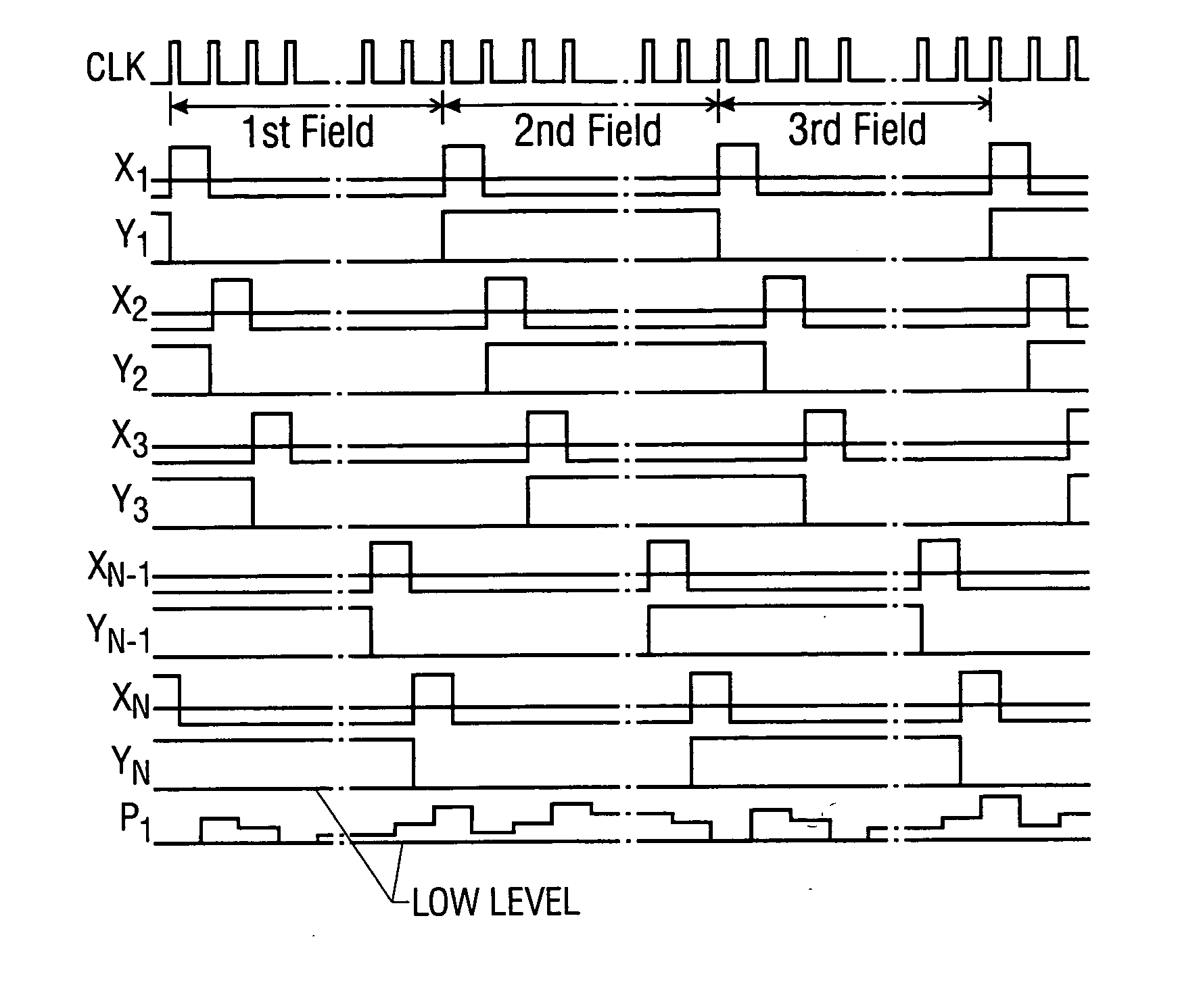
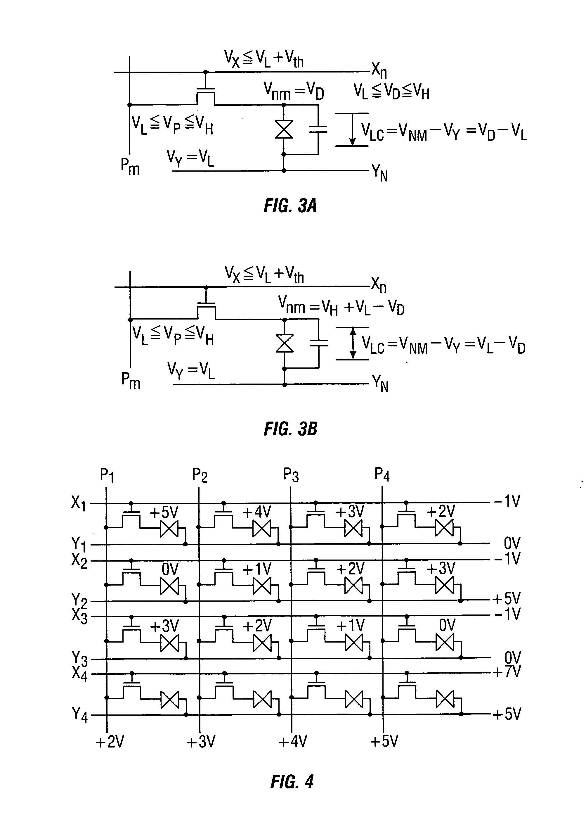
[0061]FIG. 1 shows a field inverting type driving method according to the invention in an N-row active matrix liquid crystal display device employing the IPS mode. In this embodiment, the same display data as shown in FIG. 8 are used. As shown in FIG. 1, in the first field, selection pulses are sequentially applied to N scan lines X1, X2, X3, . . . , XN−1, XN. At a time point when a pulse is applied to each scan line, the potential of the corresponding one of the common lines Y1, Y2, Y3, . . . , YN−1, YN decreases from the high-level (VH) to the low-level (VL). Thus, the state of FIG. 3A is realized.
[0062] Conversely, in the second field, when selection pulses are sequentially applied to the scan lines X1, X2, X3, . . . , XN−1, XN, the potentials of the corresponding common lines Y1, Y2, Y3, . . . , YN−1, YN increase from the low-level to the high-level. This the state of FIG. 3B is realized.
[0063] In the third field, the same operation as in the first field is performed. The dire...
embodiment 2
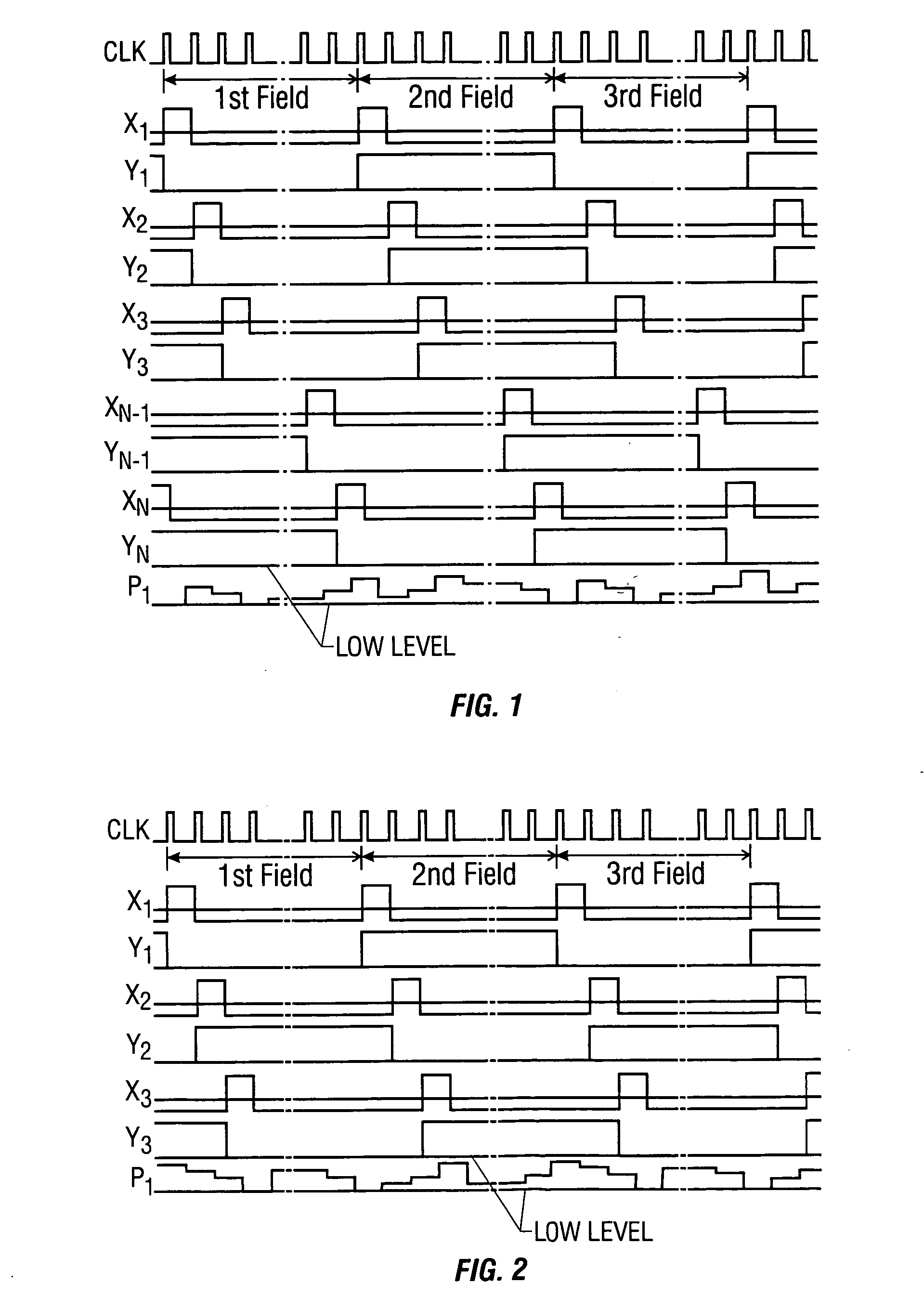
[0064]FIG. 2 shows a gate line inverting type driving method according to the invention in an N-row active matrix liquid crystal display device employing the IPS mode. As shown in FIG. 2, in the first field, the potentials of the odd-numbered common lines Y1, Y3, . . . are changed from the high-level to the low-level when selection pulses are applied to the corresponding scan lines. Conversely, the potentials of the even-numbered common lines Y2, Y4, . . . are changed from the low-level to the high-level when selection pulses are applied to the corresponding scan lines.
[0065] That is, in the first field, the state of FIG. 3A is established in the odd-numbered rows and the state of FIG. 3B is established in the even-numbered rows. Thus, a gate line inverting state is attained in which the directions of electric fields applied to the liquid crystal capacitor elements LC in adjacent rows are reverse to each other.
[0066] The operation in the second field is in converse to that in the ...
embodiment 3
[0070] Differences between the driving method of the invention and the conventional driving method will be described below with reference FIGS. 11A-11C. FIGS. 11A-11C show waveforms of the potentials of the scan line Xn, the data line Pm, and the common line Yn that are connected to the pixel shown in FIG. 7. It is assumed that the field inverting scheme is employed. This embodiment employs a scheme in which an offset voltage Voff is always superimposed on the voltage that is applied to the pixel. In FIGS. 11A-11C, the potential VX applied to the scan line Xn and the potential VP of the data line Pm are expressed with overlapping on each other, the potential VY of the common line Vn is drawn separately with VC used as a reference potential when it varies over time (FIGS. 11B and 11C), to prevent the drawings from becoming unduly complex.
[0071]FIG. 11A shows the conventional driving method. The potential VY of the common line (or common electrode) Yn is kept at the constant value VC...
PUM
 Abstract
Description
Claims
Application Information
 - R&D
- Intellectual Property
- Life Sciences
- Materials
- Tech Scout
- Unparalleled Data Quality
- Higher Quality Content
- 60% Fewer Hallucinations
Browse by: Latest US Patents, China's latest patents, Technical Efficacy Thesaurus, Application Domain, Technology Topic, Popular Technical Reports.
© 2025 PatSnap. All rights reserved.Legal|Privacy policy|Modern Slavery Act Transparency Statement|Sitemap|About US| Contact US: help@patsnap.com


