Touch panel apparatus, method of detecting touch area, and computer product

Inactive Publication Date: 2006-01-26
PIONEER CORP
View PDF0 Cites 154 Cited by
  • Summary
  • Abstract
  • Description
  • Claims
  • Application Information

AI Technical Summary

Benefits of technology

[0008] It is an object of the present invention to at l

Problems solved by technology

The detection of the two t

Method used


Image

  • Touch panel apparatus, method of detecting touch area, and computer product
  • Touch panel apparatus, method of detecting touch area, and computer product
  • Touch panel apparatus, method of detecting touch area, and computer product

Examples


Embodiment Construction

[0026] Exemplary embodiments of the present invention will be explained below in detail with reference to the accompanying drawings. It should be noted that the invention will not be limited by the present embodiments.

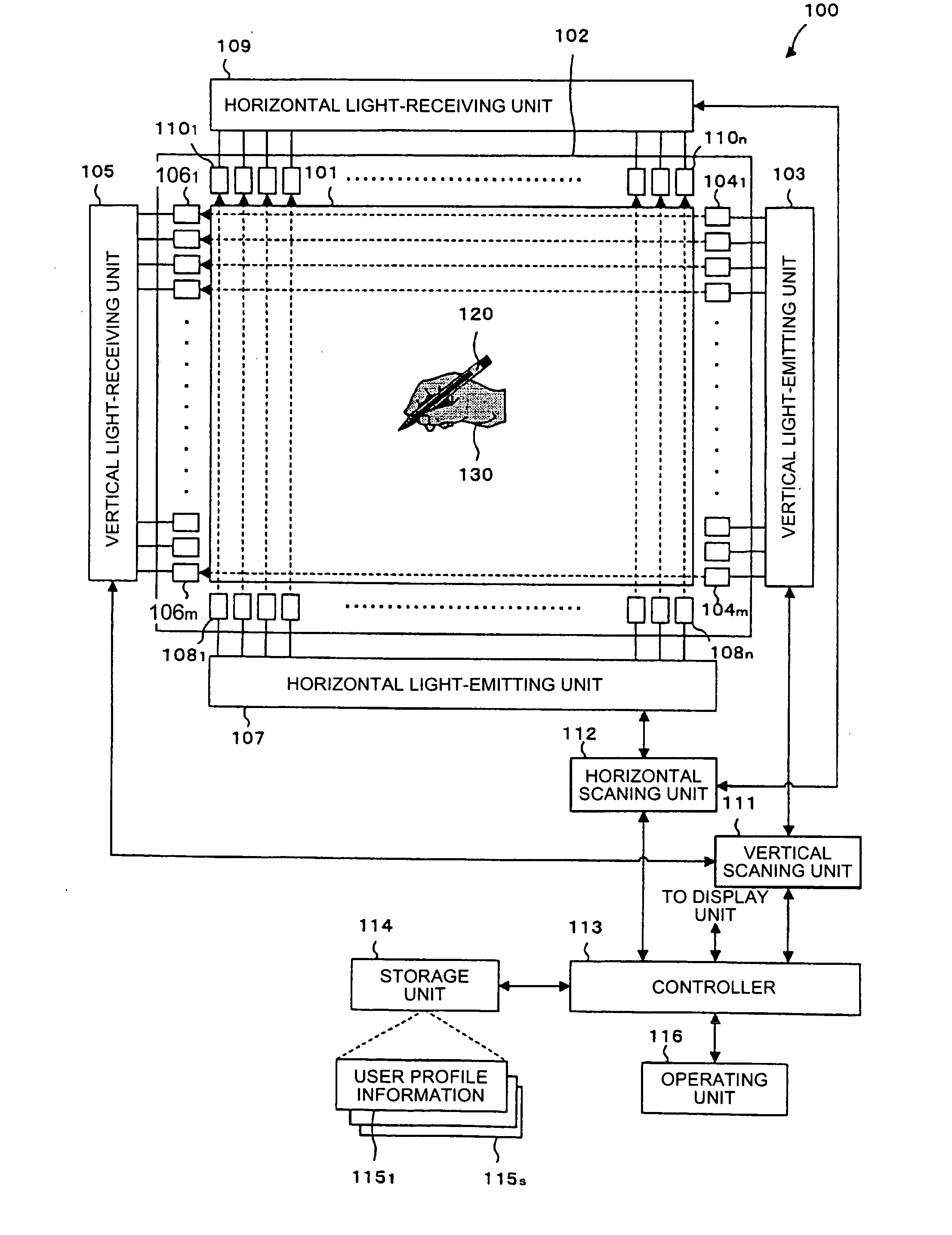
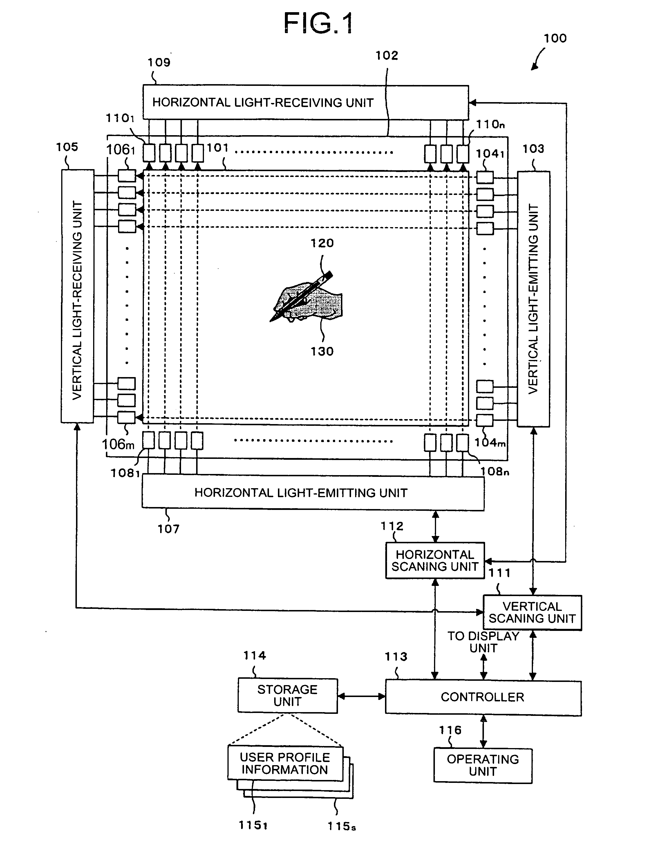
[0027]FIG. 1 is a block diagram of a touch panel apparatus 100 according to one embodiment of the present invention. In FIG. 1, a display unit 101 is an LCD, a PDP, or a CRT, which displays various kinds of information. A touch panel 102 is provided on the surface of the display unit 101. The touch panel 102 detects a touch area (expressed by x-y coordinates, for example) on which a touch pen 120 held in a hand 130 touches.

[0028] A vertical light-emitting unit 103 and a vertical light-receiving unit 105 are disposed opposite to each other on both vertical sides of the display unit 101, and have functions of emitting light (including an infrared ray) and receiving light respectively. In other words, the vertical light-emitting unit 103 and the vertical light-receiving...


PUM


Abstract

A touch panel apparatus includes a touch panel provided on a display; a touch-area detecting unit that detects a touch area when an object touches on a surface of the touch panel; and a determining unit that compares, when the touch-area detecting unit detects two touch areas, dimensions of the two touch areas, validates a touch area having a smaller dimension, and invalidates a touch area having a larger dimension.

Description

BACKGROUND OF THE INVENTION [0001] 1. Field of the Invention [0002] The present invention relates to a technology for preventing an error due to detection of two touch areas in a touch panel apparatus. [0003] 2. Description of the Related Art [0004] Conventionally, a touch panel apparatus that detects a position touched with a touch pen or a finger on coordinates is proposed (see, for example, Japanese Patent Application Laid-open Nos. 2002-149348, 2001-312370, and 2001-306241). The touch panel apparatus has a touch panel provided on the surface of a liquid-crystal display (LCD), a plasma display panel (PDP), or a cathode ray tube (CRT). The touch panel detects a position on coordinates at which a touch pen or the like touches on the touch panel. [0005] Specifically, plural light-emitting elements (not shown) are laid out on one vertical side 11a and one horizontal side 11b of a touch panel 11 of a touch panel apparatus 10 shown in FIG. 11. Plural light-receiving elements (not shown...

Claims


Application Information

Patent Timeline
IPC IPC(8): G09G5/00
CPCG06F3/0421G06F3/0418G06F3/04186
Inventor OKANO, AKIHIRO
Owner PIONEER CORP
Why Eureka
Try Eureka