Anterior composite matrix dental restoration system

a composite matrix and dental restoration technology, applied in the field of dental tools and equipment, can solve the problems of most common decay in more difficult areas to clean, most difficult to treat, and most difficult to clean cavities and fillings, and achieve the effect of great comfor

Inactive Publication Date: 2006-01-26
YATES DAVID W
View PDF13 Cites 27 Cited by
  • Summary
  • Abstract
  • Description
  • Claims
  • Application Information

AI Technical Summary

Benefits of technology

[0024] The dentist using the present system need only place the matrix in position to partially encircle the tooth and cover the filling material, and then hold the matrix dam in place by means of the special forceps tool as the filling material cures. The relatively small forceps tool provides considerably greater comfort for both the patient and the dentist or technician by precluding the need to hold one's fingers within the mouth of the patient as the composite filling material cures. The same tool used for installation of the matrix, for holding the matrix in place during the curing of the filling material, for removing the matrix after the filling material has cured.

Problems solved by technology

The process is delicate and exacting, to insure that the filling material is properly placed and shaped to avoid discomfort or future problems for the patient.
Decay most often occurs in more difficult areas to clean, e.g., along the gum line and between teeth.
Class III cavities and fillings, i.e., those which occur between teeth, are perhaps the most difficult to treat due to the immediate proximity of the adjacent tooth.
In one case, adhesives have been applied to the matrices to hold them in place, but the adhesives have often been found ineffective in the oral environment, and when they do work, often result in pulling the freshly applied filling composite from the tooth when the dam is removed.
This is clearly uncomfortable for both the patient and the dentist or technician.
Moreover, the Croll matrix is opaque due to its metal construction, and cannot pass ultraviolet light therethrough to provide curing of composite materials which set or cure by exposure to such ultraviolet light.

Method used


Image

  • Anterior composite matrix dental restoration system
  • Anterior composite matrix dental restoration system
  • Anterior composite matrix dental restoration system

Examples


Embodiment Construction

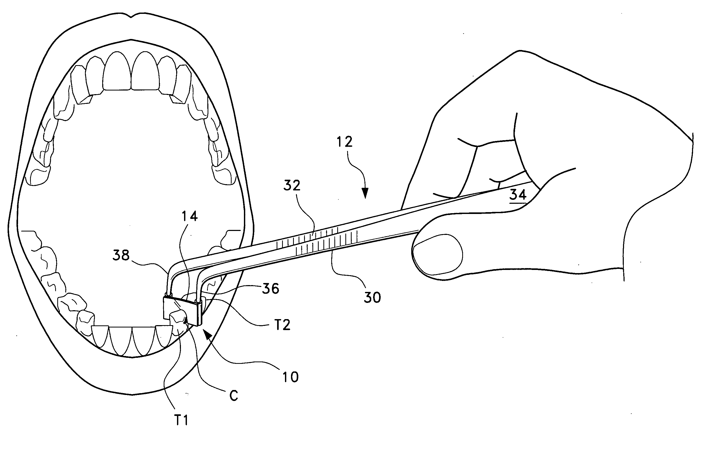
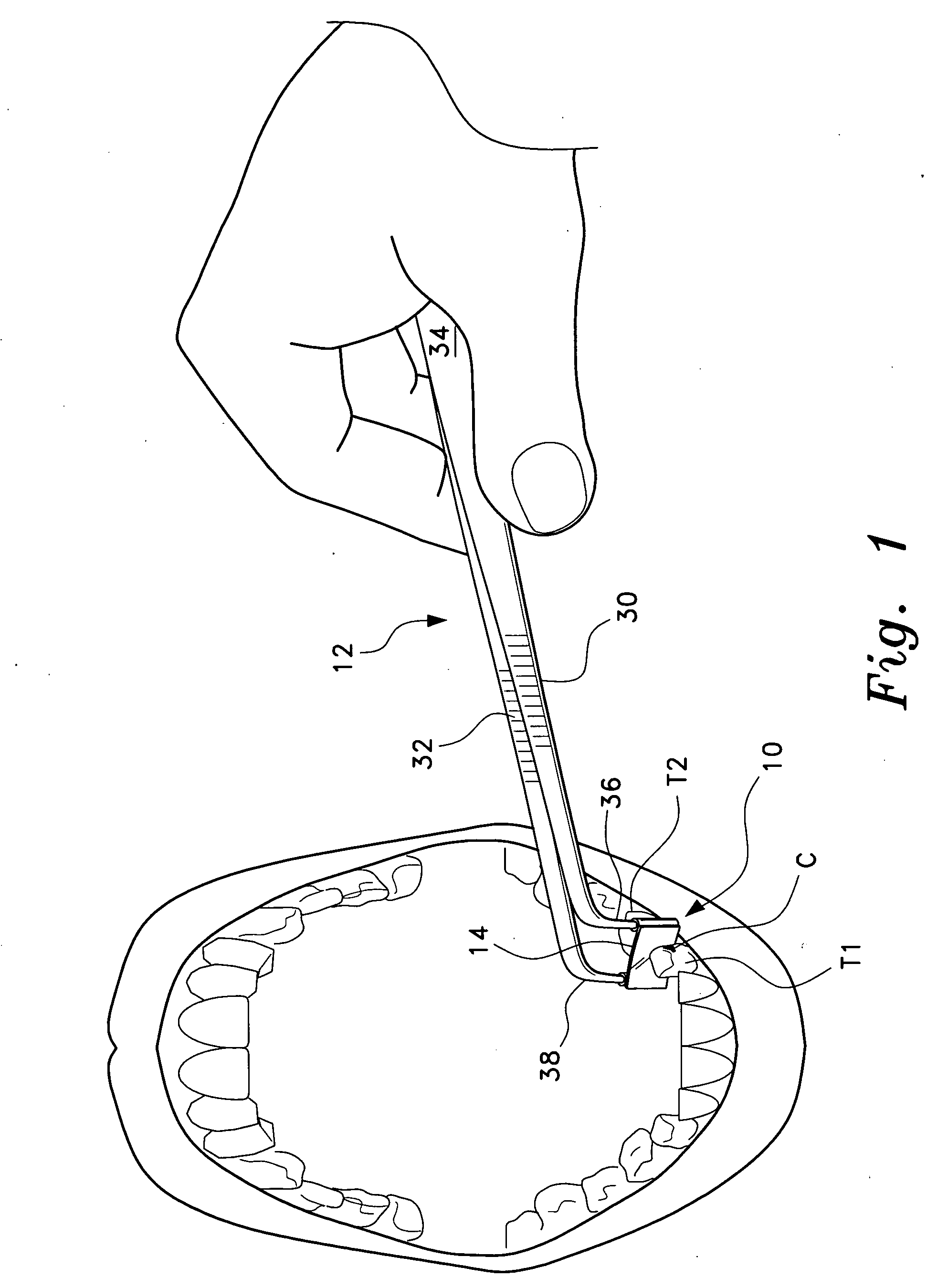
[0034] The present invention comprises various embodiments of an anterior composite matrix dental restoration system, i.e., a dental matrix and a manipulation tool therefor, for use in holding a filling material in place in a front (anterior) tooth as the filling material sets or cures in the previously prepared tooth. FIG. 1 of the drawings provides an illustration showing an exemplary installation of the present matrix 10 between two adjacent anterior teeth T1 and T2, with the forwardmost tooth T1 having a freshly prepared cavity C therein. Dental caries, such as the cavity C, often form between teeth due to trapped food lodging between the teeth that supports decay-causing bacteria. These between-the-teeth cavities are classified as class III, when they extend along the side of a tooth, although they may approach the front and back of the tooth as well, or more technically, cavities in the proximal surfaces of incisors and cuspids or canines not requiring removal of the incisal a...


PUM


Abstract

The anterior composite matrix dental restoration system provides a matrix for holding a composite filling material in place as it cures, and a tool for holding the matrix in place during the curing of the filling material. The matrix comprises a thin, flat, flexible, and transparent sheet of plastic material with parallel tubular extensions on the opposite ends. The distal ends of the specialized forceps tool are inserted into the tubular ends of the matrix and used to install, hold, and remove the matrix. The relatively small and narrow tool greatly increases the comfort of both patient and dentist or dental technician by precluding need to insert and hold the fingers in the mouth of the patient to install, hold, and remove the matrix. The matrices may be provided in different sizes, with at least the tubular end components being optionally color coded to indicate the corresponding size.

Description

BACKGROUND OF THE INVENTION [0001] 1. Field of the Invention [0002] The present invention relates generally to dental tools and equipment, and more specifically to a small matrix or dam which is placed about an anterior tooth to hold the composite filling material in place during the curing process. The matrix includes fittings on each end thereof adapted for engagement by a tool for installing and removing the matrix, the installation and removal tool in combination with the matrix forming the system. [0003] 2. Description of the Related Art [0004] Dental work and repair is perhaps the most commonly required and performed medical procedure in the United States. The majority of such work, other than periodic checkups and cleaning, is the repair or filling of dental caries. The process is delicate and exacting, to insure that the filling material is properly placed and shaped to avoid discomfort or future problems for the patient. [0005] Decay most often occurs in more difficult area...

Claims


Application Information

Patent Timeline
Patent Type & Authority Applications(United States)
IPC IPC(8): A61C5/04A61C3/14
CPCA61C5/125A61C5/85
Inventor YATES, DAVID W.
Owner YATES DAVID W
Why Eureka
Try Eureka