Self-traveling cleaner

a self-traveling, cleaner technology, applied in carpet cleaners, electric equipment installation, carpet sweepers, etc., can solve the problems of large power consumption, difficulty in traveling, and large load on the floor surface of the self-traveling cleaner with the rotary brush

Inactive Publication Date: 2006-02-02
SANYO ELECTRIC CO LTD
View PDF6 Cites 155 Cited by
  • Summary
  • Abstract
  • Description
  • Claims
  • Application Information

AI Technical Summary

Benefits of technology

[0017] As described above, according to the self-traveling cleaner of the present invention, the brush mechanism is subjected to a small load by a floor surface, and the brush mechanism is prevented from entangling a cord or the like and interfering with self-travel.

Problems solved by technology

However, the self-traveling cleaner with the rotary brush 7 is subjected to a great load by the floor surface with rotation of the rotary brush 7 because of a large contact area between the rotary brush 7 and the floor surface.
This causes a drawback of a need for large power for rotatingly driving the rotary brush 7.
Accordingly, the main body 61 self-travels dragging the cord 91, which can cause a problem of a difficulty in traveling.

Method used


Image

  • Self-traveling cleaner
  • Self-traveling cleaner
  • Self-traveling cleaner

Examples


Embodiment Construction

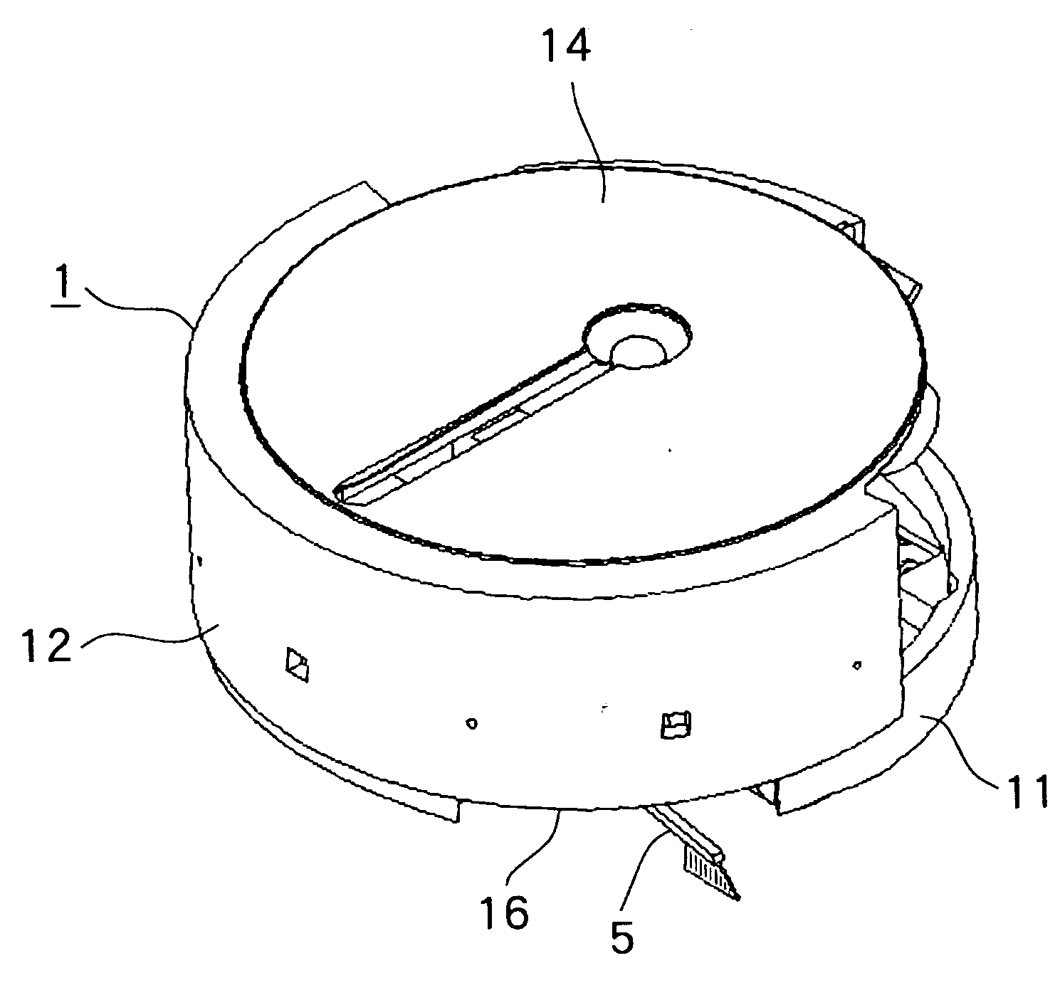
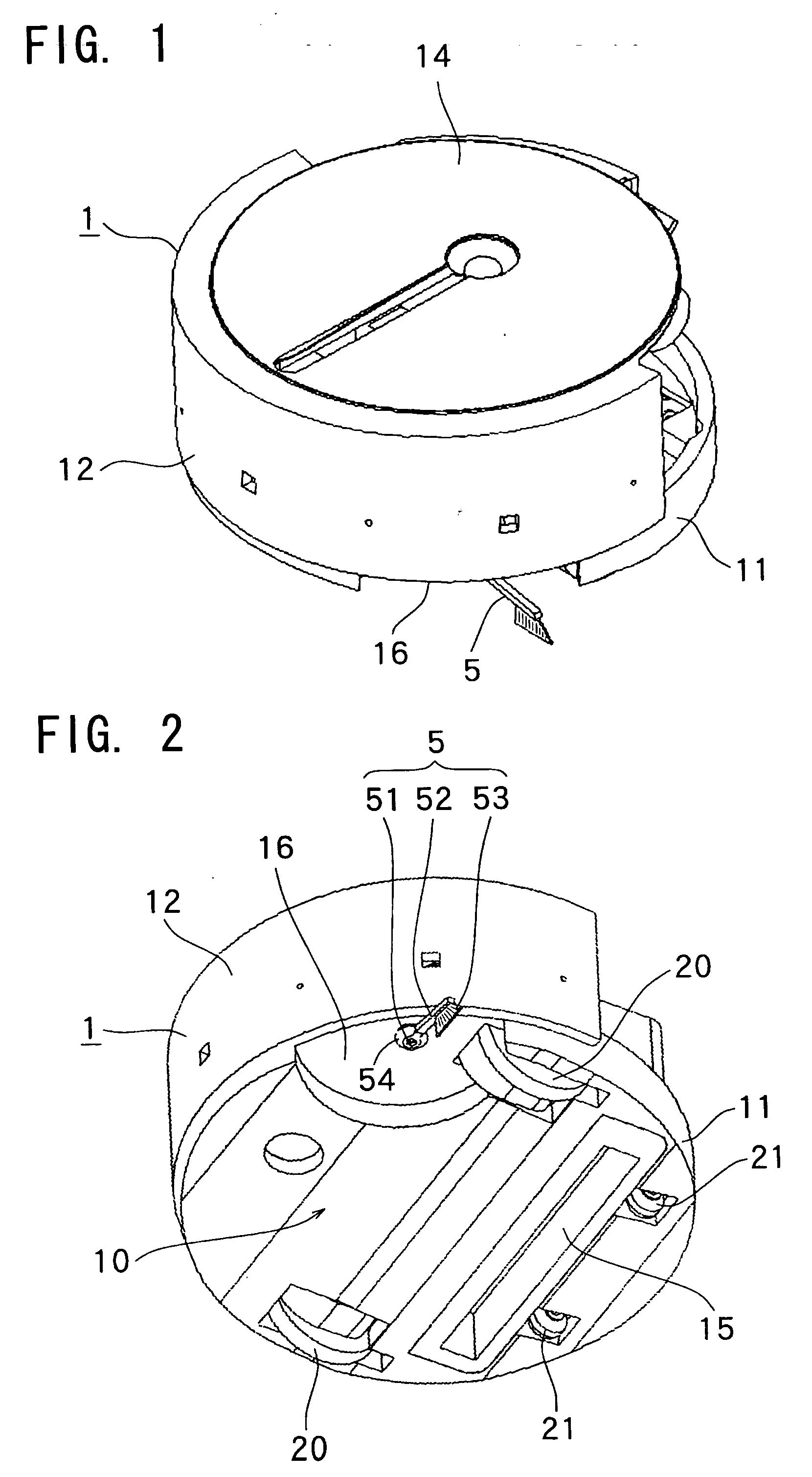
[0029] An embodiment of the present invention will be described below in detail with reference to the drawings. As shown in FIG. 1, a self-traveling cleaner of the present invention includes a main body 1, which is cylindrical as a whole. An end portion of a brush mechanism 5 projects from an outer periphery of the main body 1.

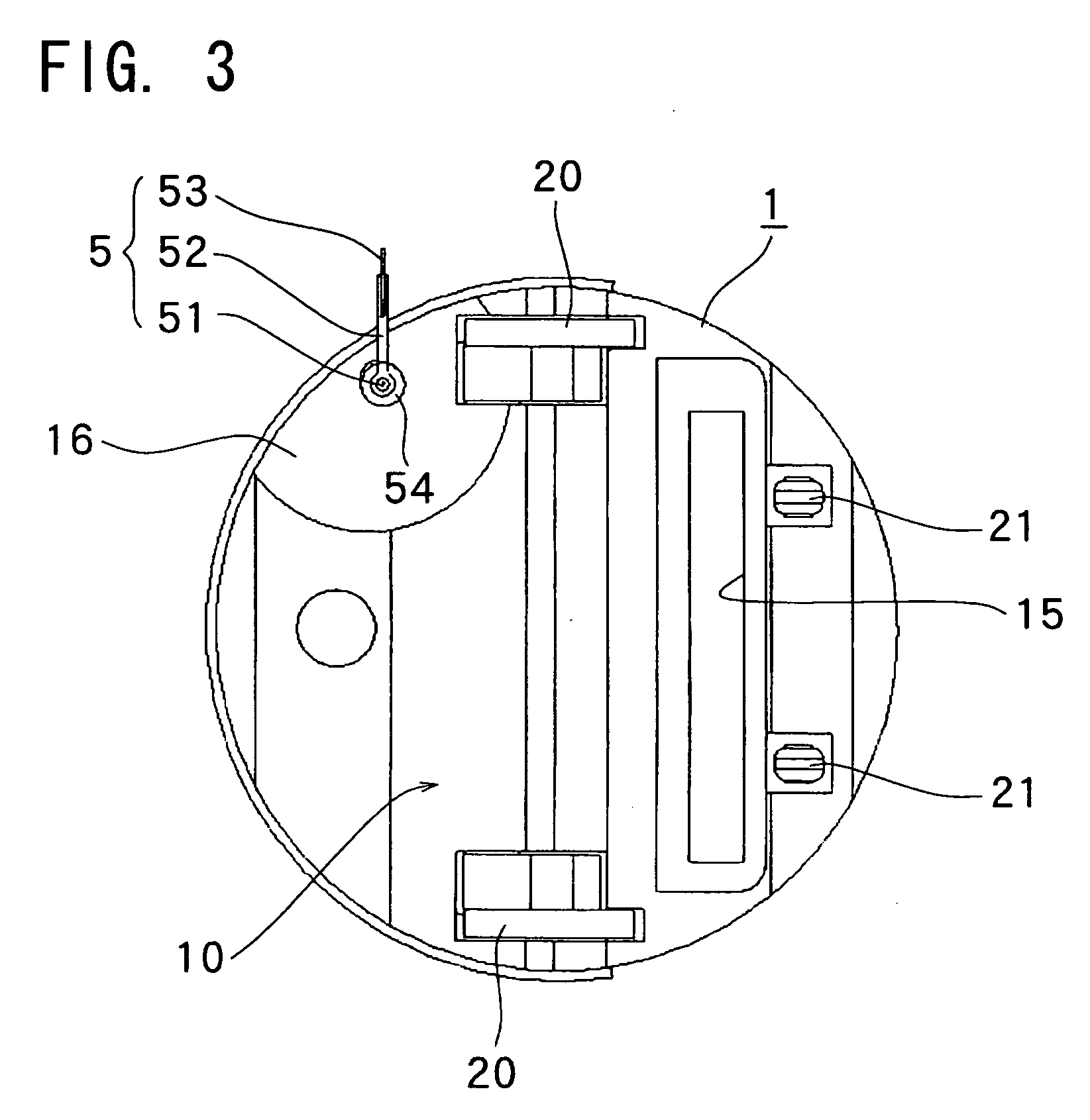
[0030] As shown in FIGS. 2 and 3, the main body 1 has a reverse side 10 provided with a pair of driving wheels 20, 20 and a pair of auxiliary wheels 21, 21. The brush mechanism 5 is horizontally rotatably provided in a depression 16 formed on a part of the reverse side 10. An inlet 15 is further provided on the reverse side 10 of the main body 1.

[0031] The brush mechanism 5 includes a rotation axis 51 extending perpendicular to a floor surface, one arm 52 made of elastic resin projecting laterally from a lower end of the rotation axis 51, and a brush 53 planted on an end portion of the arm 52 toward the floor surface. Furthermore, as shown in FIGS. 5 and 6, ...


PUM


Abstract

In a self-traveling cleaner of the present invention, a cleaning mechanism includes a brush mechanism rotatable along a floor surface and a driving mechanism for rotatingly driving the brush mechanism. The brush mechanism includes a rotation axis extending perpendicular to the floor surface, one arm projecting laterally from a lower end of the rotation axis, and a brush planted on the arm. The rotation axis is provided within a reverse side of the main body, and the arm has a rotation angle range in which the arm projects outwardly from an outer periphery of the main body and a rotation angle range in which the arm is contained within the outer periphery of the main body.

Description

[0001] The priority application Number 2004-222340 upon which this patent application is based is hereby incorporated by reference. BACKGROUND OF THE INVENTION [0002] 1. Field of the Invention [0003] The present invention relates to a self-traveling cleaner that self-travels on a floor surface to clean the floor surface. [0004] 2. Description of Related Art [0005] Various self-traveling cleaners have been conventionally proposed (see JP 2003-114719 A, JP 5-228090 A, JP 7-032752 B, JP 0.8-089453 A, JP 2001-258806 A, and JP 2004-195215 A). For example, a self-traveling cleaner shown in FIG. 8 includes a cylindrical main body 61 having a self-traveling mechanism including a pair of driving wheels 62, 62 and a pair of auxiliary wheels 63, 63, etc. and a cleaning mechanism including a circular rotary brush 7, etc. As shown in FIG. 9, the main body 61 includes a dust collector 74 having an inlet 75, and a driving mechanism including a driven pulley 71, a belt 72, and a driving pulley 73, ...

Claims


Application Information

Patent Timeline
Patent Type & Authority Applications(United States)
IPC IPC(8): A47L11/24
CPCA47L2201/00A47L9/009A47L9/28A47L9/00
Inventor NISHIKAWA, MASATO
Owner SANYO ELECTRIC CO LTD
Why Eureka
Try Eureka