Waste disposal device including a cartridge movable by rollers

a technology of a waste disposal device and a roller, which is applied in the directions of waste collection, transportation and packaging, packaging, etc., can solve the problems of affecting the appearance of waste packages, the knotting of tubing, and the inconvenience of diaper pails, so as to achieve the effect of convenient removal from the hamper

Inactive Publication Date: 2006-02-02
ANGELCARE USA LLC
View PDF13 Cites 46 Cited by
  • Summary
  • Abstract
  • Description
  • Claims
  • Application Information

AI Technical Summary

Benefits of technology

[0039] To allow for easy removal of the series of encapsulated waste packages from the container, a pail, or another comparable removable waste receptacle, may be placed in the container on a base for receiving the encapsulated waste packages and an access door is formed in an outer wall of the container to enable removal and emptying of the pail. The pail may be lined with a trash bag so that when the pail is removed, the trash bag

Problems solved by technology

A twist rim is rotatably coupled to the cartridge such that rotation of the twist rim causes twisting of the tubing.
A major inconvenience of diaper pails of the “Diaper Genie”™ type is that it is necessary to manually tie both ends of the tubing to use the diaper pail.
The necessary, multiple tyings of the tubing is bothersome and moreover, when the knots are not made sufficiently strong, unpleasant odors emanating from the waste packages can escape through the knots.
Another problem with diaper pails of the “Diaper Genie”™ type is that cutting the tubing is difficult and requires the use of a manually operable cutting instrument.
This cutting instrument does not enable easy cutting of the tubing.
Yet another problem with diaper pails of the “Diaper Genie”™ type is that the series of waste packages are removed from the diaper pail through an access door pivotally connected to the bottom end of the container.
The series of wa

Method used


Image

  • Waste disposal device including a cartridge movable by rollers
  • Waste disposal device including a cartridge movable by rollers
  • Waste disposal device including a cartridge movable by rollers

Examples


first embodiment

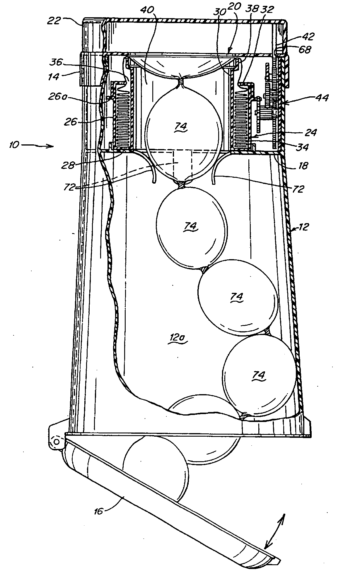
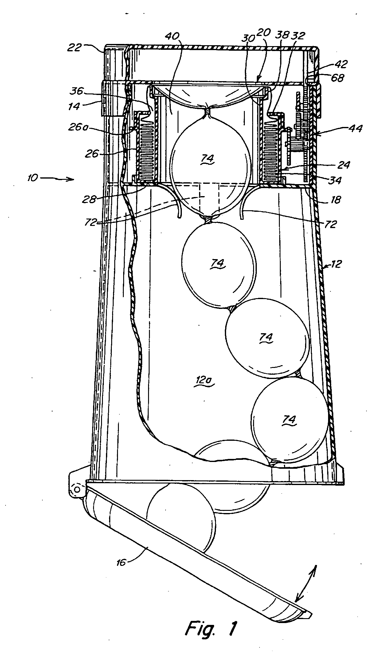
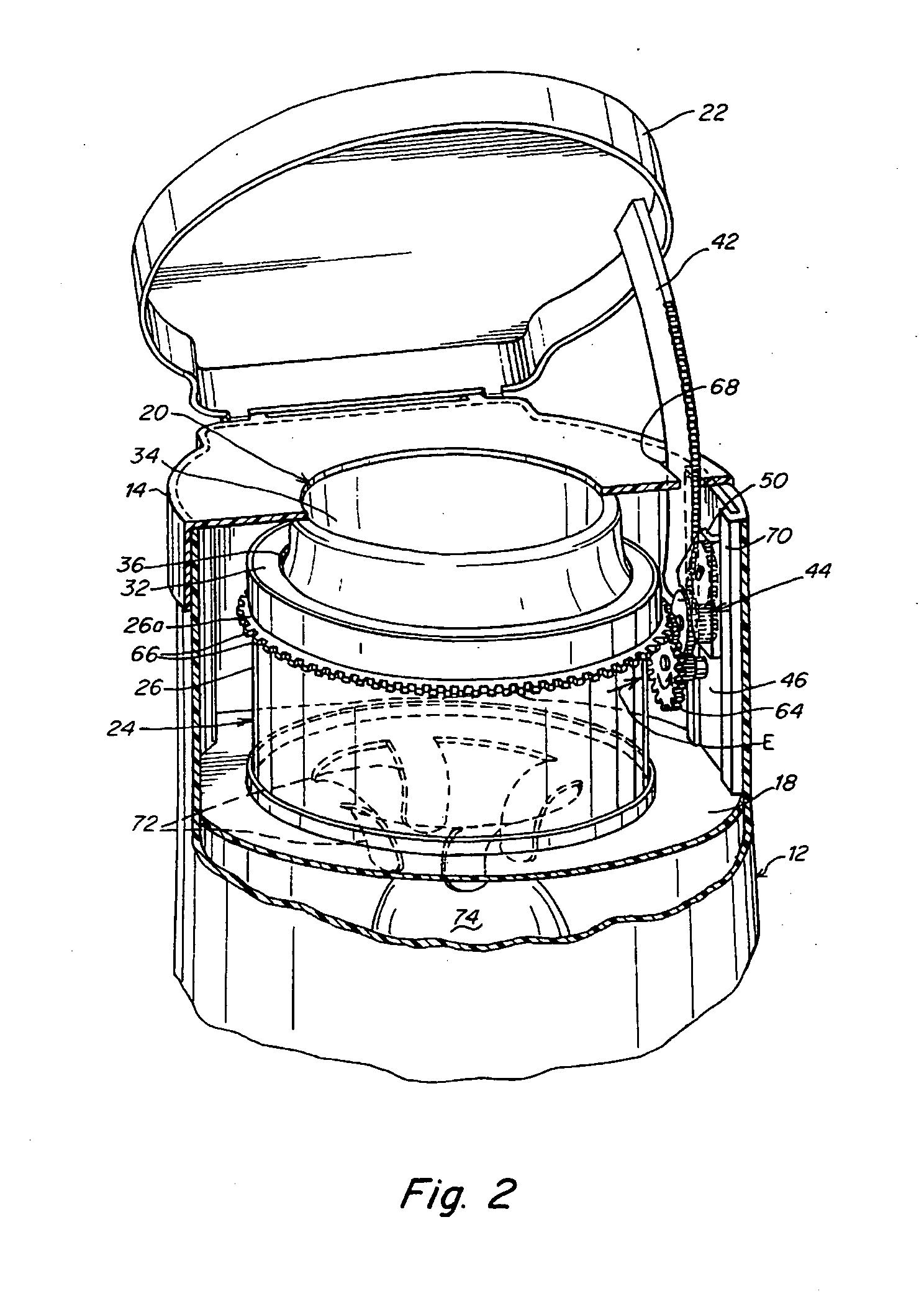
[0129] such a waste disposal device is shown in FIGS. 7-9 and it incorporates a rotation mechanism for rotating the waste package relative to the cartridge. The waste disposal device 80 includes a substantially cylindrical container 82 having an outer wall 84, and a base 86 arranged at a lower end of the outer wall 84. A removable hamper 88 is provided and has a wall 88a which also constitutes a part of the outer wall 84 of the container 82. The waste packages accumulate in the hamper 88 and the hamper 88 is removed from the container 82 and emptied when full. Since the hamper 88 comes into direct contact with the waste packages and is liable to become dirty, it is advantageous that it is detachable from the container 82 so that it can be easily cleaned, possibly by placing it in a dishwasher.

[0130] A lid 22 is pivotally connected to the outer wall 84 so as to be movable between an open position in which a waste insertion opening 20 is exposed to enable insertion of a waste package ...


PUM

PropertyMeasurementUnit
Shapeaaaaaaaaaa

Abstract

A waste disposal device including a cartridge movable by rollers. The waste disposal device comprises a rotation mechanism for rotating the rotatable cartridge. The cylindrically shaped waste disposal device has an inner wall. The rotatable cartridge comprises a cylindrical shape having an outside wall. The rotation mechanism comprising at least two opposingly aligned movable rollers extends between said inner wall of said waste disposal device and said outer wall of said rotatable cartridge. The rollers are engagingly configured to cause the cartridge to rotate upon activation of the rotation mechanism.

Description

CROSS-REFERENCE TO RELATED APPLICATIONS [0001] This application is a continuation-in-part (CIP) of application Ser. No. 10 / 693,087, filed on Oct. 23, 2003, which is a continuation of application Ser. No. 10 / 456,428, filed on Jun. 6, 2003, which is a continuation of application Ser. No. 10 / 138,058, filed on May 2, 2002, now U.S. Pat. No. 6,612,099, which claims benefit under 35 U.S.C. § 119(e) of U.S. provisional application Ser. No. 60 / 288,186 filed on May 02, 2001; U.S. provisional application Ser. No. 60 / 337,355, filed on Nov. 8, 2001, and U.S. provisional application Ser. No. 60 / 359,148, filed on Feb. 20, 2002.FIELD OF INVENTION [0002] The present invention relates generally to waste disposal devices using packs of flexible tubing, and more particularly, to improved health care apparatus for the sanitary and odorless packaging and disposal of diapers and similar or related waste, medical waste, industrial waste and any other waste wherein sanitary and substantially odorless dispo...

Claims


Application Information

Patent Timeline
IPC IPC(8): B65B9/15B65B67/12B65F1/06B65F1/10B65F1/12B65F1/14
CPCB65B9/15B65B67/1277B65F1/062B65F2240/132B65F1/1426B65F2210/1675B65F2230/15B65F1/12
Inventor STRAVITZ, DAVID M.CHOMIK, RICHARD S.YOHO, MARK
Owner ANGELCARE USA LLC
Why Eureka
Try Eureka