System and method for channel scanning in wireless networks

a wireless network and channel scanning technology, applied in the field of wireless stations and networks, can solve the problems of difficult prediction of wireless stations and possibility of domain changes, and achieve the effect of maximizing the scanning speed of wireless stations staying within a domain

Active Publication Date: 2006-02-02
NTT DOCOMO INC
View PDF22 Cites 75 Cited by
  • Summary
  • Abstract
  • Description
  • Claims
  • Application Information

AI Technical Summary

Benefits of technology

[0021] It is an object of the present invention to enable any wireless station that moves across a domain boundary to comply with the changed regulation of the new domain. The scanning speed of the wireless stations staying within a domain is also preferably maximized. According to one aspect of the present invention, a pre-alert field is provided in a data block.

Problems solved by technology

Because of the mobility of a wireless station, it is very difficult for a wireless station to predict whether upcoming access points are in the same domain.
There would be a possibility of domain change when wireless stations attempt channel scanning.

Method used


Image

  • System and method for channel scanning in wireless networks
  • System and method for channel scanning in wireless networks
  • System and method for channel scanning in wireless networks

Examples


Embodiment Construction

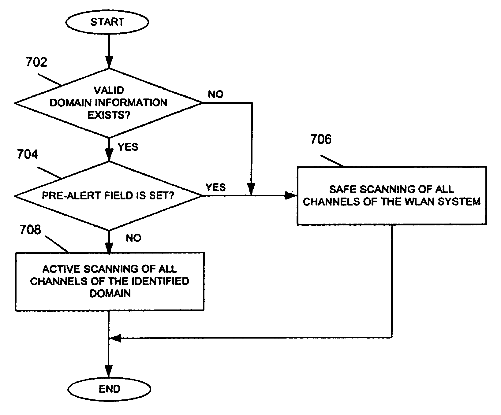
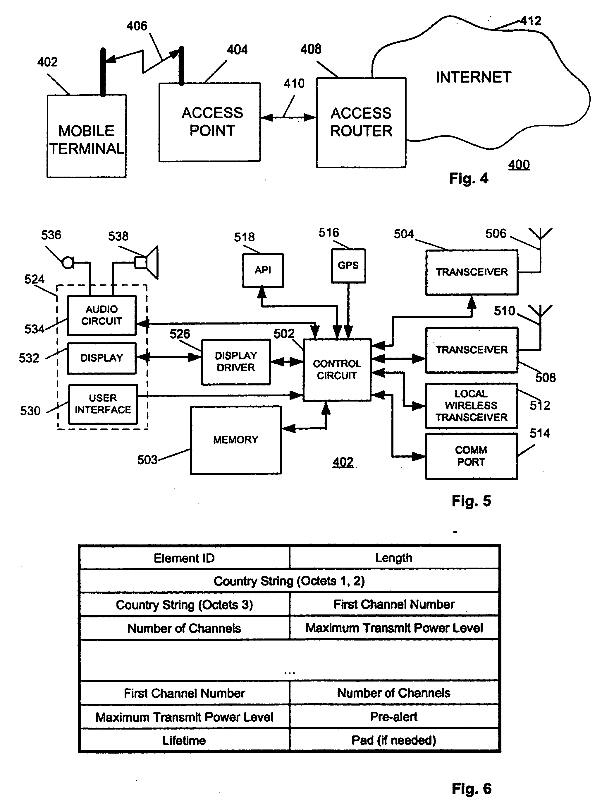
[0037]FIG. 4 shows a block diagram of a wireless communication network employing embodiments of the present invention. A wireless station (mobile terminal) 402 is coupled to an access point 404 by a wireless communication link 406. The access point 404 is coupled to an access router 408 by a communication link 410. The access router 408 is coupled to a communication network, such as the Internet 412.

[0038]FIG. 5 shows a block diagram of the wireless station 402 according to one embodiment of the present invention. The wireless station 402 preferably includes a control circuit 502, such as a microprocessor, microcontroller, ASIC or other circuits or integrated circuits used to control the wireless station 402. A memory device 503 could also be coupled to the control circuit 502. The control circuit 502 is also coupled to a first transceiver 504 having an antenna 506, and a second transceiver 508 having an antenna 510. The wireless station 402 could also include a local wireless tran...


PUM


Abstract

Channel scanning for wireless networks, such as Wireless Local Area Networks (WLANs), generally provides a wireless station with the information on the available WLAN resources, such as the frequency band and the maximum transmission power. The present invention provides safe and fast domain-aware channel scanning, enabling a wireless station to comply with applicable local regulations, in spite of the possibility of domain changes, with short channel-scanning time. Fast channel scanning is accomplished by active channel scanning if valid domain information is available and there is no possibility of domain change. Also, domain-independent channels, if any, are first scanned using active scan to get domain information faster.

Description

CROSS-REFERENCE TO RELATED APPLICATIONS [0001] This application claims the benefit of Provisional Application Nos. 60 / 438,964, filed Jan. 9, 2003, and 60 / 492,689, filed Aug. 5, 2003. The present application incorporates the disclosure of these provisional applications by reference.BACKGROUND OF THE INVENTION [0002] 1. Field of the Invention [0003] The present invention relates generally to wireless stations and networks, and more particularly to a method of scanning channels in a wireless network. [0004] 2. Description of the Related Art [0005] Regulatory domains, such as individual nations, independently determine the frequency band and the maximum transmission power allowed for wireless communication systems. The conditions established by each regulatory domain may vary significantly even for the same wireless communication system. For example, while the 4.9-5.0 gigahertz (GHz) band is allowed for IEEE802.11a wireless local area network (WLAN) in Japan, the 4.94-4.99 GHz band is r...

Claims


Application Information

Patent Timeline
Patent Type & Authority Applications(United States)
IPC IPC(8): H04Q7/24H04L12/28H04L12/56H04W12/00H04W36/32H04W48/10H04W48/16
CPCH04W48/16Y02D30/70
Inventor JEONG, MOO RYONGGAO, XIAWATANABE, FUJIOWU, GANG
Owner NTT DOCOMO INC
Why Eureka
Try Eureka