Road sheltering and optimization

a shelter structure and road technology, applied in the direction of renewable energy generation, greenhouse gas reduction, roads, etc., can solve the problems of reducing contributing to global warming, and causing thousands of deaths and injuries, so as to reduce the air resistance of vehicles and maximize the energy drawn from the air. , the effect of increasing wind speed

Inactive Publication Date: 2011-05-19
RACZKOWSKI RAYMOND
View PDF26 Cites 54 Cited by
  • Summary
  • Abstract
  • Description
  • Claims
  • Application Information

AI Technical Summary

Benefits of technology

[0019]The present invention can further comprise a method for sheltering and optimizing the use of a road comprising: (a) covering a road with an enclosed structure spanning over the road; (b) coupling a solar panel to the structure to convert sunlight to usable power; (c) coupling a wind turbine to the structure to convert wind energy to usable power; and (d) providing a vertical wind turbine within the structure to collect energy and redirect the flow of air exiting the vertical wind turbine with the flow of traffic on the road to decrease air resistance against the traffic.
[0020]Critical to the design of the road shelter is that the velocity of the air current increases substantially as it flows over, across, and through the road shelter, thereby maximizing the energy drawn from the air by the wind turbines. As air approaches the road shelter from the side, the arcuate shape of the road shelter forces the air upward, and the air accelerates much like the design of an airplane wing. The accelerated air is then redirected toward and through wind turbines to capitalize on the increased wind speeds.
[0021]It is believed that wind turbines are not otherwise suitable for use in areas that do not have a sufficient average constant wind velocity to make the wind turbines an economically viable solution. However, the road shelter's inherent design can increase the ambient wind speed by 20% or more, thereby making wind turbines a realistic solution for many more locations than was previously known. In addition, the efficiency of a wind turbine increases exponentially as the wind speed increases. Therefore, the design of the road shelter creates an increase in wind speed which it is able to collect and maximize.

Problems solved by technology

Millions of vehicles travel these labyrinths of road each day producing emissions harmful to the environment and contributing to global warming.
Each year, inclement weather and poor road conditions such as wet or icy roads cause accidents resulting in thousands of deaths and injuries.
No system yet exists for sheltering a road while efficiently using surrounding natural resources.
Thus, air current provided by traffic is not constant, and simply using air flow from vehicles to drive wind turbines is not a viable solution in many areas.

Method used


Image

  • Road sheltering and optimization
  • Road sheltering and optimization
  • Road sheltering and optimization

Examples


second embodiment

[0034]In a second embodiment, at least one vertical wind turbine is located in a median of the road and secured to portions of the structural support beams. At least one horizontal turbine can also be provided which extends above the cover, and which is driven by air current flowing over the cover.

third embodiment

[0035]In a third embodiment, an electrolytic cell is provided which performs electrolysis of water stored in a water storage tank filled by a drainage system which collects rain water running off of the cover.

fourth embodiment

[0036]In a fourth embodiment, an elevated rail is located near the cover on either the inside or outside of the structure.

[0037]It is to be appreciated by one having ordinary skill in the art that the described road shelter may be one of multiple identical “grid pieces” that can be connected in sequence to create a road shelter stretching many miles.

[0038]The following description of the preferred embodiment is merely exemplary in nature and is in no way intended to limit the invention, its application, or uses.

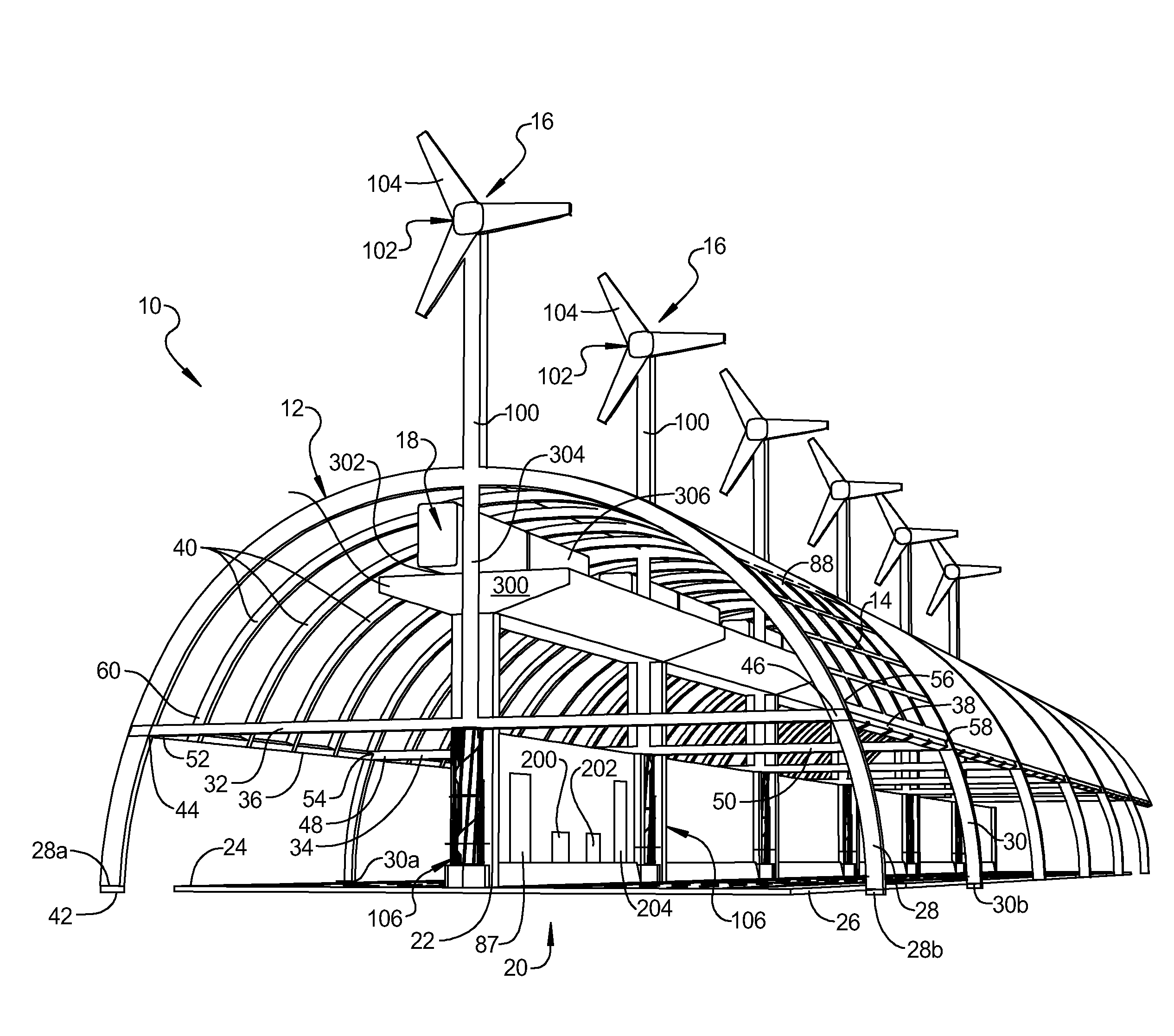
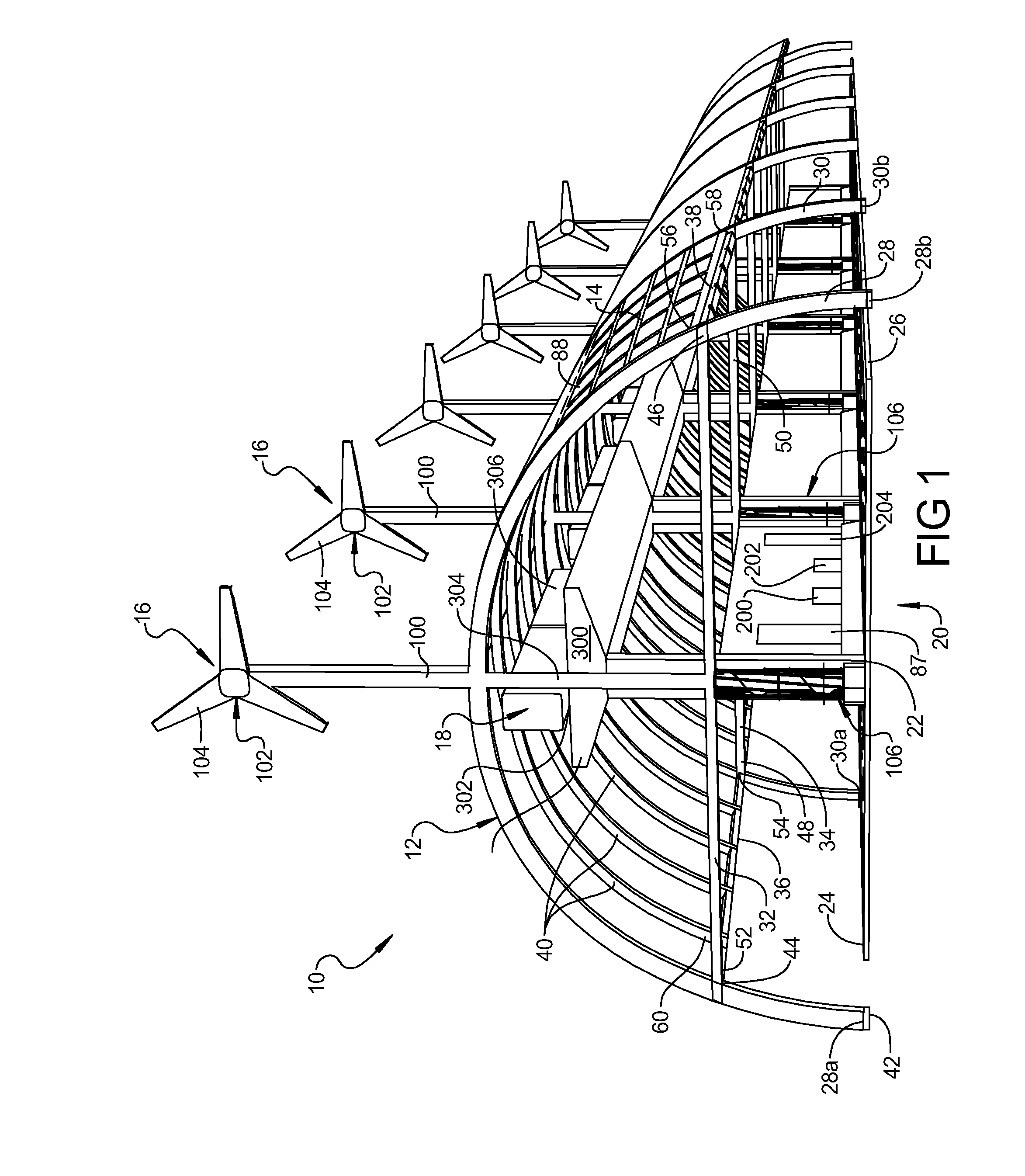
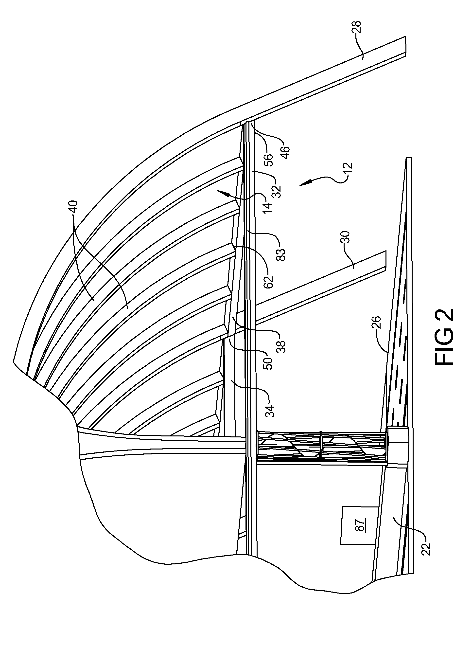
[0039]With reference to FIGS. 1 and 2 of the drawings, a road shelter constructed in accordance with the teachings of the present invention is generally identified by the reference numeral 10. The road shelter 10 includes a structural frame 12, a cover 14, elevated wind turbines 16, and an elevated rail 18. The structure 12 is designed to span over a road or highway 20 having a median 22 and road edges 24 and 26, for example a U.S. Interstate highway.

[0040]In this exemplary e...


PUM


Abstract

A structure for sheltering and optimizing highway systems includes an arcuate structure extending over a highway and a cover over the structure to create an enclosure. The enclosure protects the highway and users of the highway from rain, snow and sun while the surrounding scenery remains visible to drivers. A number of different additions optimize use of the highway. For example, a plurality of solar panels are layered on the cover and wind turbines are used to create usable energy, an air current generation system reduces wind resistance on vehicles to increase gas mileage, and an elevated rail system transports many persons great distances along the highway.

Description

CROSS-REFERENCE TO RELATED APPLICATION[0001]This application claims the benefit of U.S. Provisional Application 61 / 262,398 which was filed on Nov. 18, 2009, the entire disclosure of which is hereby incorporated by reference, including all drawings and formal papers.BACKGROUND OF THE INVENTION[0002]1. Field of the Invention[0003]The present invention relates to a road shelter structure. More particularly, the present invention relates to a road shelter for enclosing a portion of a road and for optimizing and collecting energy and transferring the energy into electricity and fuel sources.[0004]2. Description of Related Art[0005]The federal highway system has tens of thousands of miles of roadway stretched throughout the United States. Millions of vehicles travel these labyrinths of road each day producing emissions harmful to the environment and contributing to global warming. Each year, inclement weather and poor road conditions such as wet or icy roads cause accidents resulting in t...

Claims


Application Information

Patent Timeline
Patent Type & Authority Applications(United States)
IPC IPC(8): E04H14/00E04D13/18
CPCE01C1/002E04B7/08F03D9/007F03D11/04Y02E10/728F05B2240/213F05B2240/911F05B2240/9113F05B2240/13F03D13/20Y02E10/50Y02E10/74Y02E70/30F03D3/0427F03D9/11F03D9/25F03D9/46H02S10/12
Inventor RACZKOWSKI, RAYMOND
Owner RACZKOWSKI RAYMOND
Why Eureka
Try Eureka