
X-ray diffraction screening system convertible between reflection and transmission modes

a technology of diffraction and transmission mode, applied in the field of xray diffraction screening, can solve problems such as cross contamination in collected diffraction data

Active Publication Date: 2006-02-02
BRUKER AXS
View PDF4 Cites 10 Cited by
  • Summary
  • Abstract
  • Description
  • Claims
  • Application Information

AI Technical Summary

Benefits of technology

[0008] In accordance with the present invention, an X-ray diffraction apparatus is provided that allows X-ray diffraction analysis in either transmission or reflection mode, and provides for an easy and automatic conversion between the two modes. This differs from prior art systems, which are typically dedicated to either reflection mode or transmission mode. In the present invention, the system runs at optimum configuration for both reflection and transmission modes, and the sample library is always in the horizontal position.
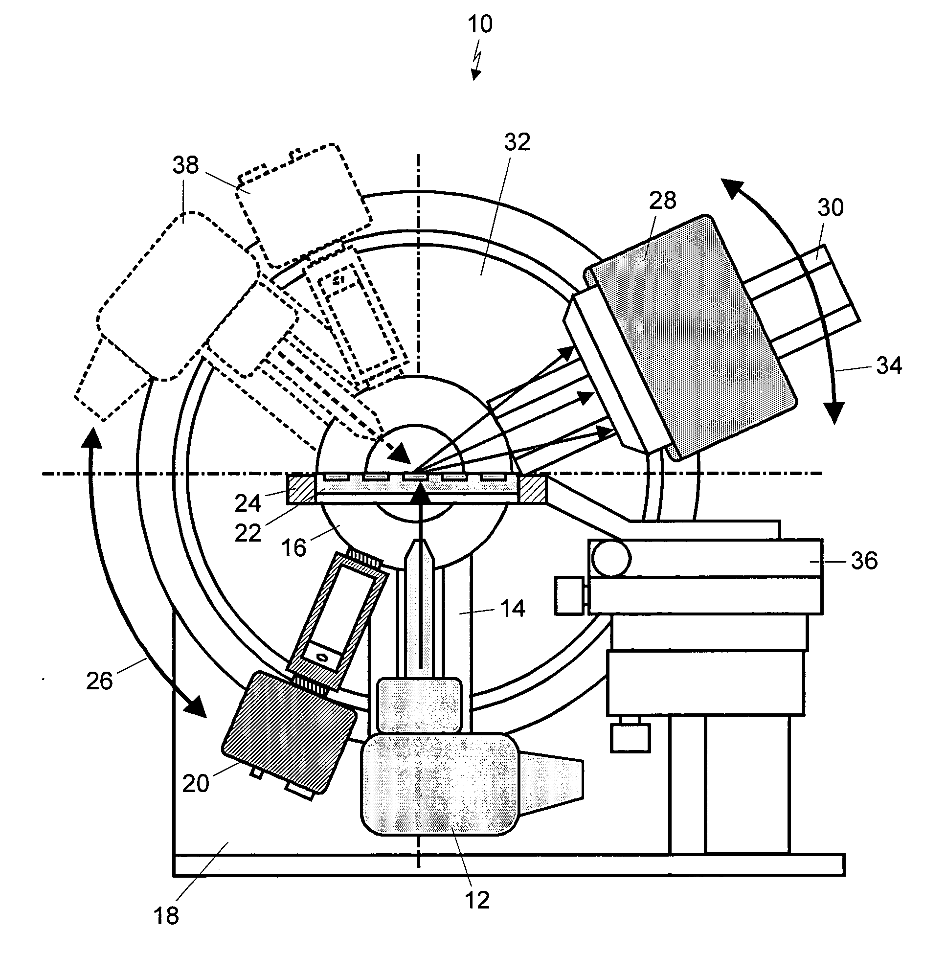
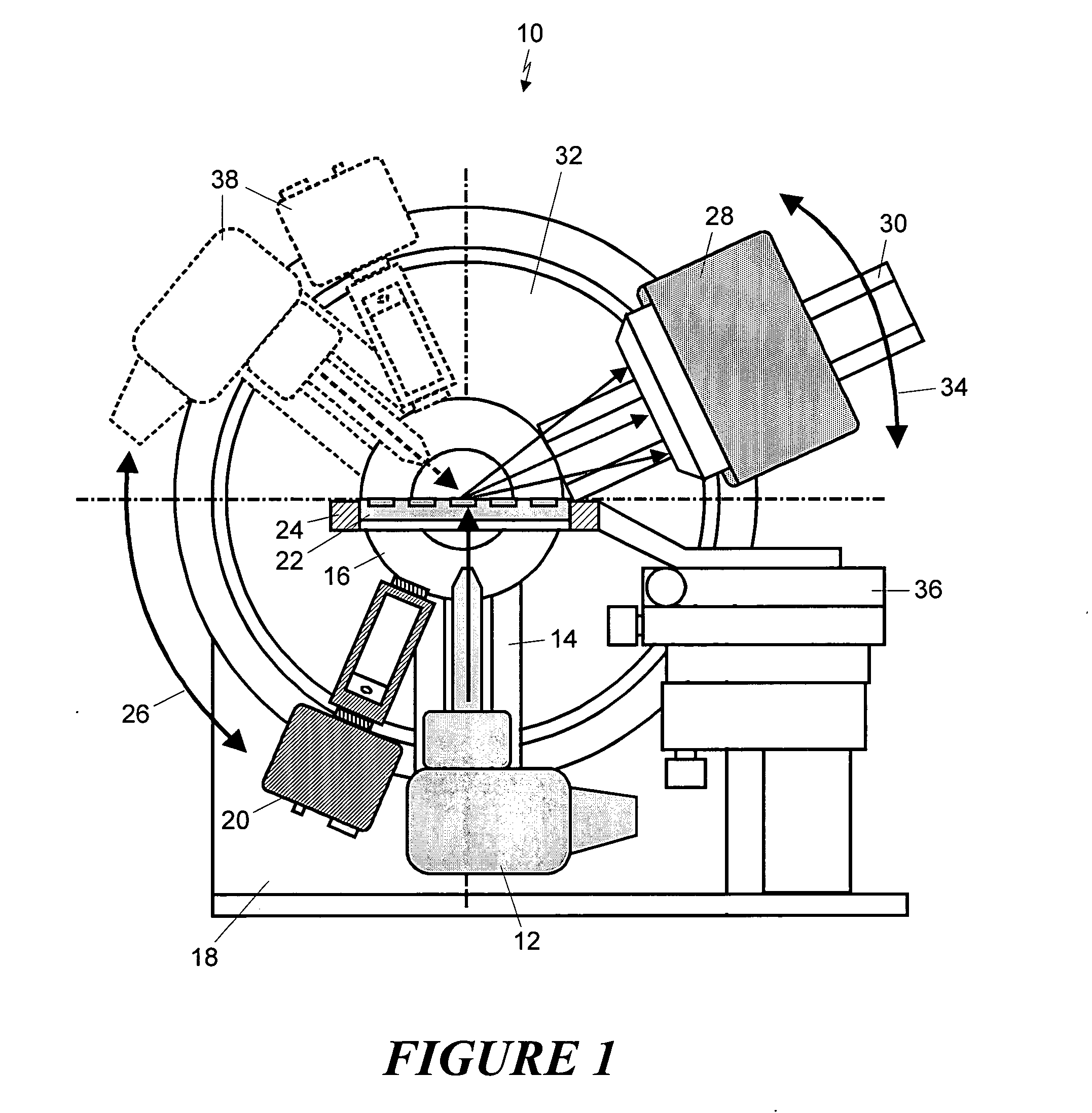
[0010] In a particular embodiment, the system is constructed using a goniometer having at least two circles that are independently rotatable. The X-ray source may be connected to a first circle of the goniometer that is movable along a predetermined path. Movement of the source assembly relocates it from a first source position, in which the X-ray energy is directed toward an upper surface of the sample holder, and a second source position, in which the X-ray energy is directed toward a lower surface of the sample holder. This allows the change from reflection to transmission mode. The X-ray detector may be connected to a second circle of the goniometer to allow it to be moved as well. In such a case, the movement of the detector might allow changes in the detector swing angle. Alternatively, the source could remain on the same side of the sample holder axis, while the detector is rotated from one side to the other to change from reflection mode to transmission mode.
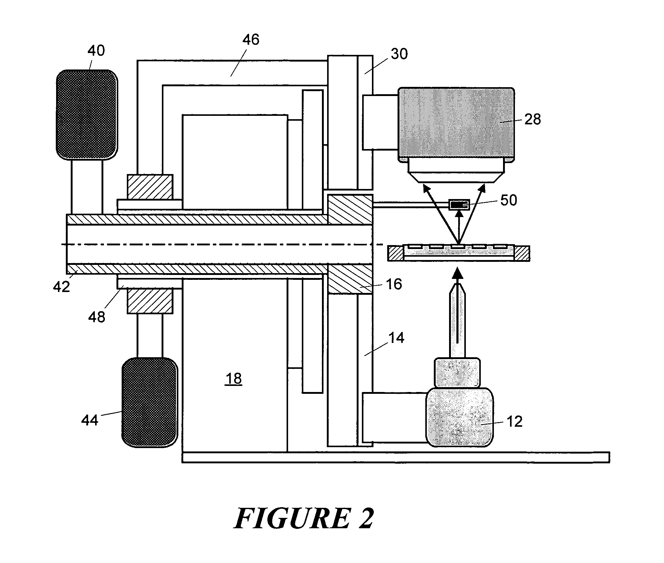
[0011] In one embodiment, the X-ray source assembly includes accompanying optics, and may be connected to an inner circle of the goniometer along with a video assembly. The detector may be connected to an outer circle of the goniometer, such that it moves free of the source and video components. A sample holder, or library, has a horizontal orientation that allows open sample containers of the library to maintain the sample without spillage. The sample library resides on a sample support that is part of the mounting assembly. The mounting assembly may also include an XYZ stage that can be adjusted to move the sample support in three dimensions, while maintaining its horizontal orientation. The XYZ stage may be offset from the location of the sample support so as to keep it from interfering with the other system components.
[0014] The movement of all of the components of the diffractometer may be computer controlled to allow automation of the detection of the entire sample library. A controller can be linked to motors that cause the rotation of the goniometer circles, as well as to motors that cause the translational movements of the XYZ stage. The controller could also operate the X-ray source and detector, for controlling the analysis of an individual sample, and use the video system for positioning the sample. With these different functionalities available, the controller could move the sample support so as to progressively align each of the samples of the sample library in the appropriate position for examination. If it was desired to change between transmission mode and reflection mode for any or all of the samples, the controller could execute the necessary movement of the system components to accomplish this. In this way, the system could be completely automated.

Problems solved by technology

Therefore, the spread beam may cause cross contamination in the collected diffraction data.

Method used


Image

  • X-ray diffraction screening system convertible between reflection and transmission modes
  • X-ray diffraction screening system convertible between reflection and transmission modes
  • X-ray diffraction screening system convertible between reflection and transmission modes

Examples


Embodiment Construction

[0018]FIG. 1 shows an illustration of the front view of an embodiment of the X-ray diffractometer 10 according to the present invention. In this arrangement, the X-ray source and optics 12 are mounted on a dovetail track 14. The dovetail track is fixed on the inner circle 16 of a vertical goniometer 18. A laser video assembly 20 is also attached to the inner circle of the goniometer. The laser video system 20 is of known configuration, and may be like that described in U.S. Pat. No. 5,359,640, which is incorporated herein by reference. A sample library 22 is supported by a sample support 24. The sample library contains a plurality of individual sample locations, which may be a series of adjacent sample wells. In operation, each of the samples is investigated individually, as the sample library may be moved to reposition the samples for each investigation.

[0019] The X-ray source, optics, and video assembly, being connected to the inner circle 16 of the goniometer 18, may be moved be...


PUM


Abstract

An X-ray diffraction apparatus provides analysis in either transmission or reflective mode and easy conversion between the two modes. An X-ray source and X-ray detector are each connected to a different circle of a goniometer. The two circles may be rotated independently to position the source and detector on the same side of a sample library for reflection mode operation, or on opposite sides of the sample library for transmission mode operation. The sample library has a horizontal orientation that allows open sample containers of the library to maintain the sample without spillage, and it connects to an XYZ stage that can move in three dimensions. The system may use a beamstop, and the goniometer and XYZ stage be motorized and controlled for automated sample analysis.

Description

CROSS-REFERENCE TO RELATED APPLICATION [0001] This application takes priority from U.S. Provisional Patent Application Ser. No. 60 / 592,037, filed Jul. 29, 2004.FIELD OF THE INVENTION [0002] The present invention relates, generally, to X-ray diffraction screening and, more particularly, to X-ray diffraction screening of sample libraries for combinatorial chemistry. BACKGROUND OF THE INVENTION [0003] Combinatorial chemistry refers to techniques to collect, test, and store the resulting data for a material library containing tens, hundreds or even thousands of different materials or compounds. Combinatorial investigations require rapid screening techniques to test and evaluate variations of composition, structure and property within a material library. X-ray diffraction is one of the most suitable screening techniques because abundant information can be revealed from the diffraction pattern, and the technique is fast and non-destructive. [0004] Combinatorial screening with X-ray diffra...

Claims


Application Information

Patent Timeline
IPC IPC(8): G01N23/20
CPCG01N23/20016
Inventor HE, BOB BAOPINGBOLLIG, RYAN C.
Owner BRUKER AXS
Learn More