Center supported bond joint

a center support and bonding technology, applied in the direction of auxillary welding devices, soldering apparatus, ways, etc., can solve the problems of weaker bonded rail joint bars b>30/b> with less electrical insulation capability, and high price of non-metallic rail joint bars

Inactive Publication Date: 2006-02-09
PORTEC RAIL PRODS
View PDF6 Cites 14 Cited by
  • Summary
  • Abstract
  • Description
  • Claims
  • Application Information

AI Technical Summary

Problems solved by technology

However, these non-metallic rail joint bars are very expensive because of the special high-performance material needed to endure the high tensile and flexural forces exerted on a rail joint bar as the wheels of a locomotive or rail car pass over the rail joint bar.
However, these epoxies will oftentimes peel off of the bonded rail joint bar 30, particularly at the center where the tensile and flexural forces are the highest, thereby resulting in a weaker bonded rail joint bar 30 with less electrical insulating capability.

Method used


Image

  • Center supported bond joint
  • Center supported bond joint
  • Center supported bond joint

Examples


Embodiment Construction

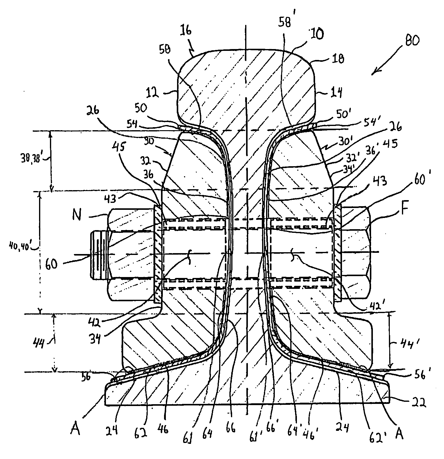
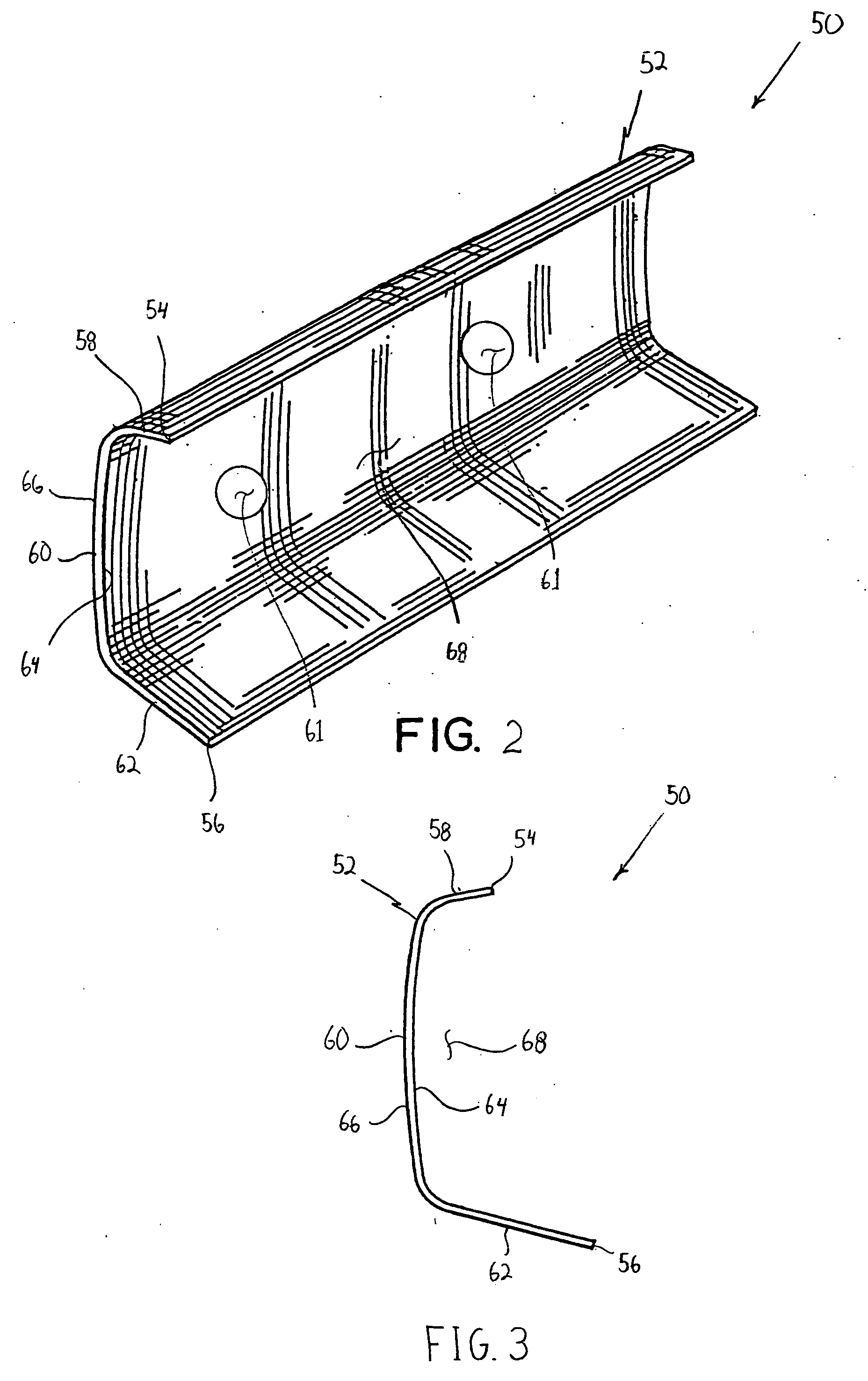
[0023] Referring to FIGS. 2-4, the present invention provides a center support sleeve 50 that is adapted to be sandwiched between a center portion of a prior art rail joint bar 30 and a pair of railroad rails 10, 10′ (designated as area A1 shown in FIG. 8). The support sleeve 50 extends partially around the rail joint bar 30 as shown in FIG. 4 in order to spread the impact loads of the rail cars away from the center portion of the rail joint bar 30. The sleeve 50, which has an end profile similar to the back surface 36 of the prior art rail joint bar 30 includes a body 52 having a first end 54 and a second end 56 and defining a head portion 58, a web portion 60 and a base portion 62. The body 52 of the sleeve 50 includes a first surface 64 and a second surface 66, wherein the head portion 58 depends from the web portion 60, which depends from the base portion 62. The head portion 58 and the base portion 62 are bent in a direction toward the first surface 64 of the web portion 60, th...


PUM

PropertyMeasurementUnit
tensile strengthaaaaaaaaaa

Abstract

A center support sleeve for a bonded rail joint bar that includes a body having a head portion, a web portion, and a base portion. The head portion depends from the web portion, which depends from the base portion. The head portion and the base portion are bent in the same direction thereby defining a recess area therebetween. The web portion of the body also defines a plurality of holes.

Description

CROSS REFERENCE TO RELATED APPLICATION [0001] This application claims the benefit of U.S. Provisional Application No. 60 / 573,117 entitled “Center Supported Bond Joint,” filed on May 21, 2004, which is hereby incorporated by reference.BACKGROUND OF THE INVENTION [0002] 1. Field of the Invention [0003] The present invention relates to insulated rail joint bars for electrically isolating parts of a rail system from each other and, more particularly, to a center support sleeve for a bonded rail joint bar. [0004] 2. Description of Related Art [0005] A rail system, which permits more than one train to travel on one stretch of track of rail, is generally divided into sections or blocks. The purpose of dividing railroad rails of a rail system into sections is to detect the presence of a train on a section of rail at any given time. Each rail section is electrically isolated from all other sections so that a high electrical resistance can be measured over the rail section when no train is pr...

Claims


Application Information

Patent Timeline
Patent Type & Authority Applications(United States)
IPC IPC(8): E01B11/00B23K9/16B23K37/00
CPCE01B11/54
Inventor URMSON, W. THOMAS JR.MOSPAN, JOHN W.DOWNEY, JOHN M.BOARIO, PATRICK J.JAROSINKSKI, RICHARD
Owner PORTEC RAIL PRODS
Why Eureka
Try Eureka