Systems and methods for the destruction of adipose tissue

Inactive Publication Date: 2005-07-14
LIPOSONIX
View PDF99 Cites 369 Cited by
  • Summary
  • Abstract
  • Description
  • Claims
  • Application Information

AI Technical Summary

Benefits of technology

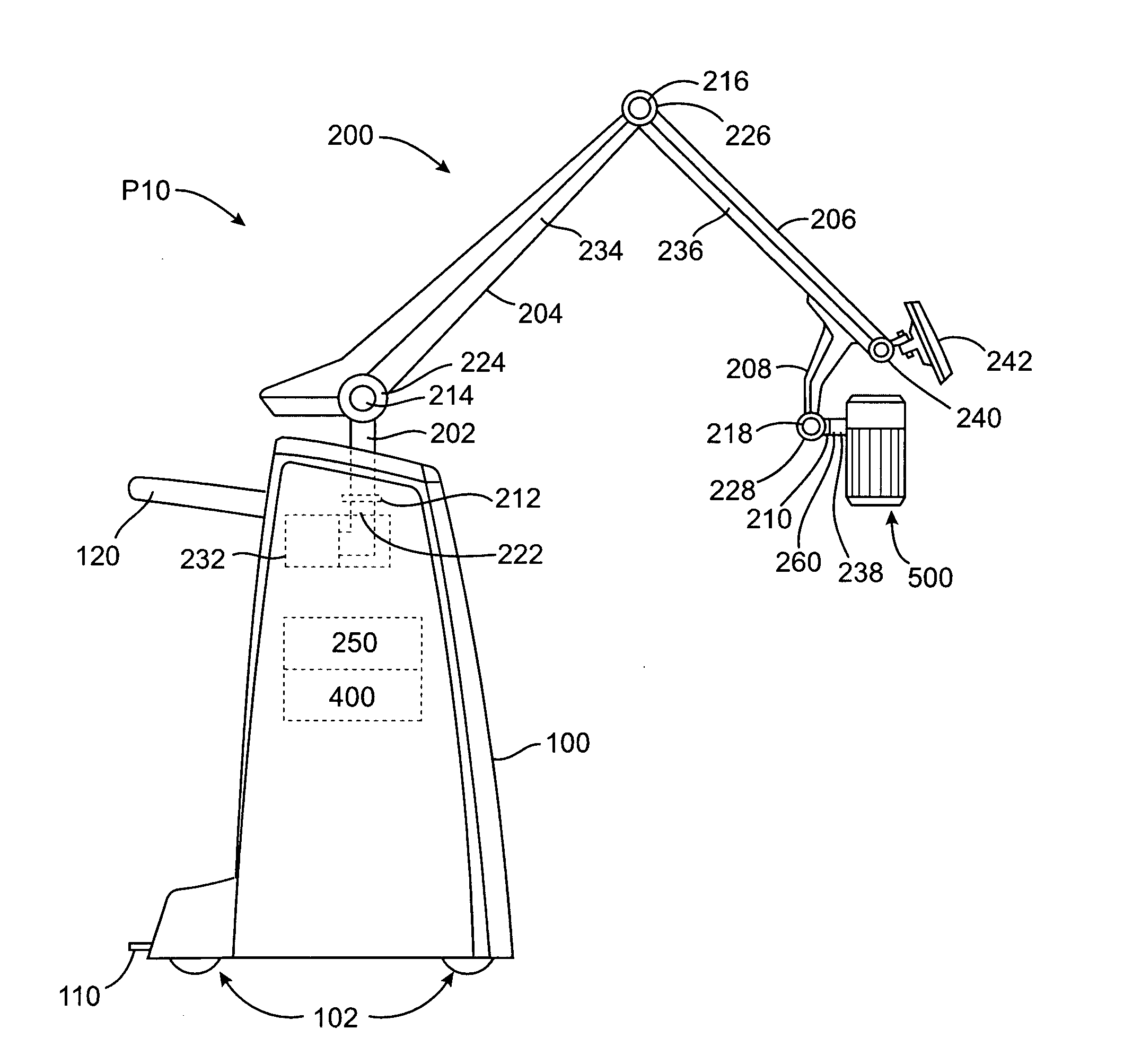
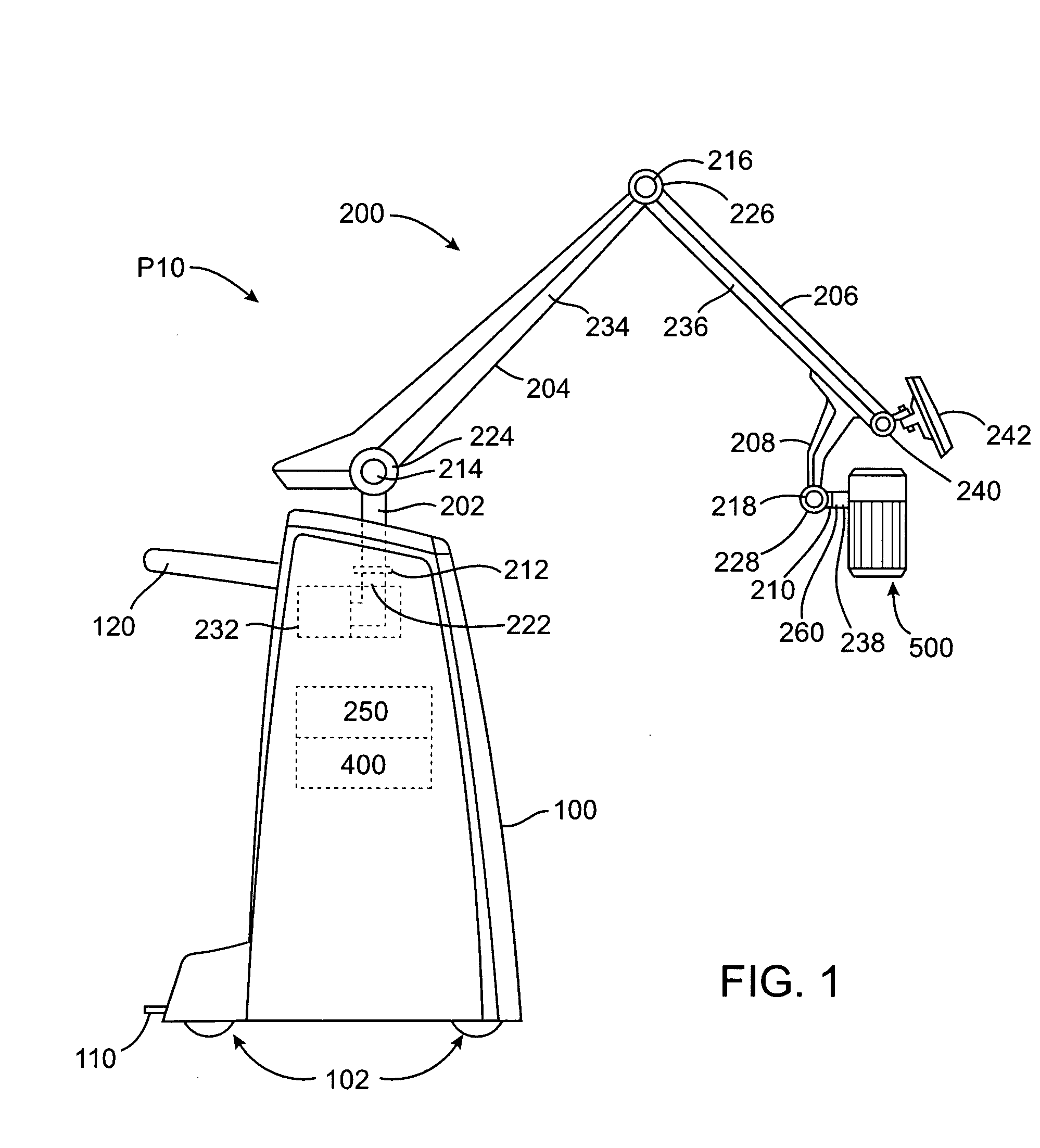
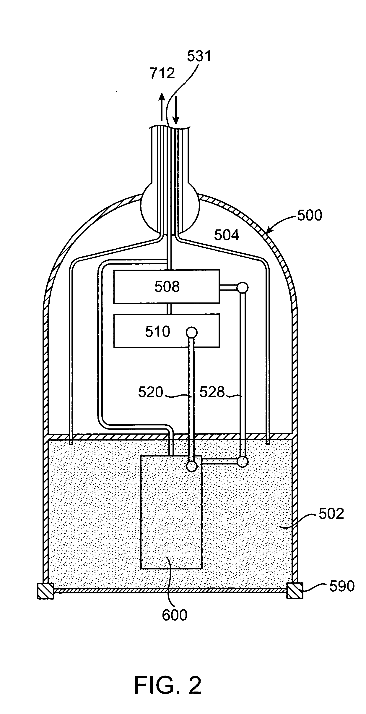
[0028] In a third embodiment there is a system for positioning a medical device, the system comprises; a robotic arm; a first control means for controlling the robotic arm; a medical device movably positioned within a therapy head, the therapy head being connected to the robotic arm; a second control means for controlling the movement of the medical device within the therapy head; and an electronic controller in electronic communication with, and for the cooperative operation of, the robotic arm, the firs

Problems solved by technology

The procedure caused bleeding, bruising, trauma, and blood loss, restricting the amount of fat removal possible.
However the procedure still removes a significant amount of structural tissue, blood and nerve endings.
This vibration disrupts the near volume fat cells and essentially liquefies them for easy removal.
Bubbles greatly increase the absorption of ultrasound and concomitant rapid heating of tissue.
These bubbles cause significant mechanical damage to tissue that can be periodically repeated by short (˜5-30 second) pulses without a lot concomitant tissue heating.
Treating a large volume of tissue can take hours with such an approach.
However ther

Method used


Image

  • Systems and methods for the destruction of adipose tissue
  • Systems and methods for the destruction of adipose tissue
  • Systems and methods for the destruction of adipose tissue

Examples


example i

[0175] Step 1: The patient comes in for an initial consultation, just as in traditional lipoplasty. If the patient decides to continue on to the procedure, dietary supplements, drugs, topical creams, etc. that may be formulated specifically to provide some benefit during or after the procedure may be provided. Examples include Bromelain and Quercetin taken prior to the procedure and Arnica Montana taken post-procedure to promote healing and reduce swelling.

[0176] Step 2: On the day of the procedure, the physician marks the patient in a manner similar to what would be done for traditional lipoplasty patients. The ink in the marking pen may contain an additional agent (e.g. an ultraviolet ink) to enhance detectability of the ink on the skin by a sensor. This may be particularly useful for dark skin colors.

[0177] Step 3: The patient is positioned for the procedure. The patient should be in the same position as he or she will be during treatment. In most case the procedure is done wit...

example ii

[0202] This method of destroying adipose tissue involves the use of the aforementioned therapy head with a simultaneous scanning and pulse wave transducer regimen. In this method the patient is prepared in the same manner as previously described. A set of contour lines are laid down to identify the area corresponding to the tissue volume to be treated (FIG. 9A). Lines or grid squares may be over laid on the contour lines (FIG. 9B). The therapy head is used to scan the tissue area to verify there is sufficient depth of adipose tissue (FIG. 9C). Once that is done, therapy may begin.

[0203] Therapy is performed by moving the scan head over the treatment block at a speed of 3 mm / sec. to 50 mm / sec., using a therapy transducer with a pulse wave mode. The robotic arm may move the transducer, or the user can move the therapy head with the instrument keeping track of the distances moved during each sweep.

[0204] The micro-positioning system can also be used with in the therapy head to sweep ...


PUM


Abstract

Described is a system and method for the destruction of adipose tissue using an energy applicator such as a HIFU transducer. The system has a scan head containing an energy applicator, a mechanical arm for carrying the weight of the scan head, and a therapy controller such as a computer for controlling the operation of the scan head. The therapy controller may be part of a general purpose computer, and may be used as a robotic controller to automate the procedure. Methods are included for destroying adipose tissue in a quick, non-invasive manner.

Description

CROSS-REFERENCES TO RELATED APPLICATIONS [0001] This application is a continuation-in-part of application Ser. No. 10 / 750,370 (Attorney Docket No. 021356-000500US), filed on Dec. 30, 2003, and a continuation-in-part of application Ser. No. 10 / 751,344 (Attorney Docket No. 021356-000600US), filed on Dec. 30, 2003. [0002] This application also claims the benefit of prior provisional application No. 60 / 533,988 (Attorney Docket No. 021356-001000US), filed on Dec. 30, 2003, and of prior provisional application No. 60 / 533,958 (Attorney Docket No. 021356-001200US), filed on Dec. 30, 2003. The full disclosures of each of the above applications is incorporated herein by reference. [0003] The subject matter of the present application is related to that of the following applications: Ser. No. 10 / 750,369, entitled “Disposable Transducer Seal”; 60 / 533,528, entitled “Position Tracking Device”; 60 / 534,036, entitled “Ultrasound Therapy Head with Movement Control”; and 60 / 534,034, entitled “Component...

Claims


Application Information

Patent Timeline
IPC IPC(8): A61B8/00A61B19/00A61F7/00A61N7/02
CPCA61B5/6843A61N2007/0008A61B8/4218A61B19/26A61B19/5212A61B19/5244A61B2019/2207A61B2019/263A61B2019/264A61B2019/464A61B2019/505A61B2019/507A61B2019/5265A61B2019/5276A61B2019/5291A61B2019/545A61N7/02A61B8/00A61N2007/0091A61B34/20A61B34/32A61B90/361A61B90/50A61B2034/105A61B2034/107A61B2034/2065A61B2090/064A61B2090/365A61B2090/378A61B2090/395A61B2090/5025A61B2090/504A61B17/00A61B17/225
Inventor QUISTGAARD, JENS U.ETCHELLS, TIMDARLINGTON, GREGORY PAULDESILETS, CHARLES S.
Owner LIPOSONIX
Why Eureka
Try Eureka