Embedded control valve using homopolar motor

a technology of homopolar motor and control valve, which is applied in the direction of valve housing, valve operating means/releasing devices, electrochemical generators, etc., can solve the problems of affecting the miniaturization effort, affecting the miniaturization effect, and affecting the design of microcells

Active Publication Date: 2006-02-09
HARRIS CORP
View PDF14 Cites 21 Cited by
  • Summary
  • Abstract
  • Description
  • Claims
  • Application Information

AI Technical Summary

Problems solved by technology

Still, microcells present a number of design challenges that will need to be overcome before these devices can be practically implemented.
Discrete components tend to be bulky, however, which oftentimes impedes miniaturization efforts.
Moreover, such control valve devices typically include pluralities of moving parts that must interoperate.
The reliability of such devices, however, is generally inversely proportional to the number of moving parts since the moving parts tend to wear.

Method used


Image

  • Embedded control valve using homopolar motor
  • Embedded control valve using homopolar motor
  • Embedded control valve using homopolar motor

Examples


Embodiment Construction

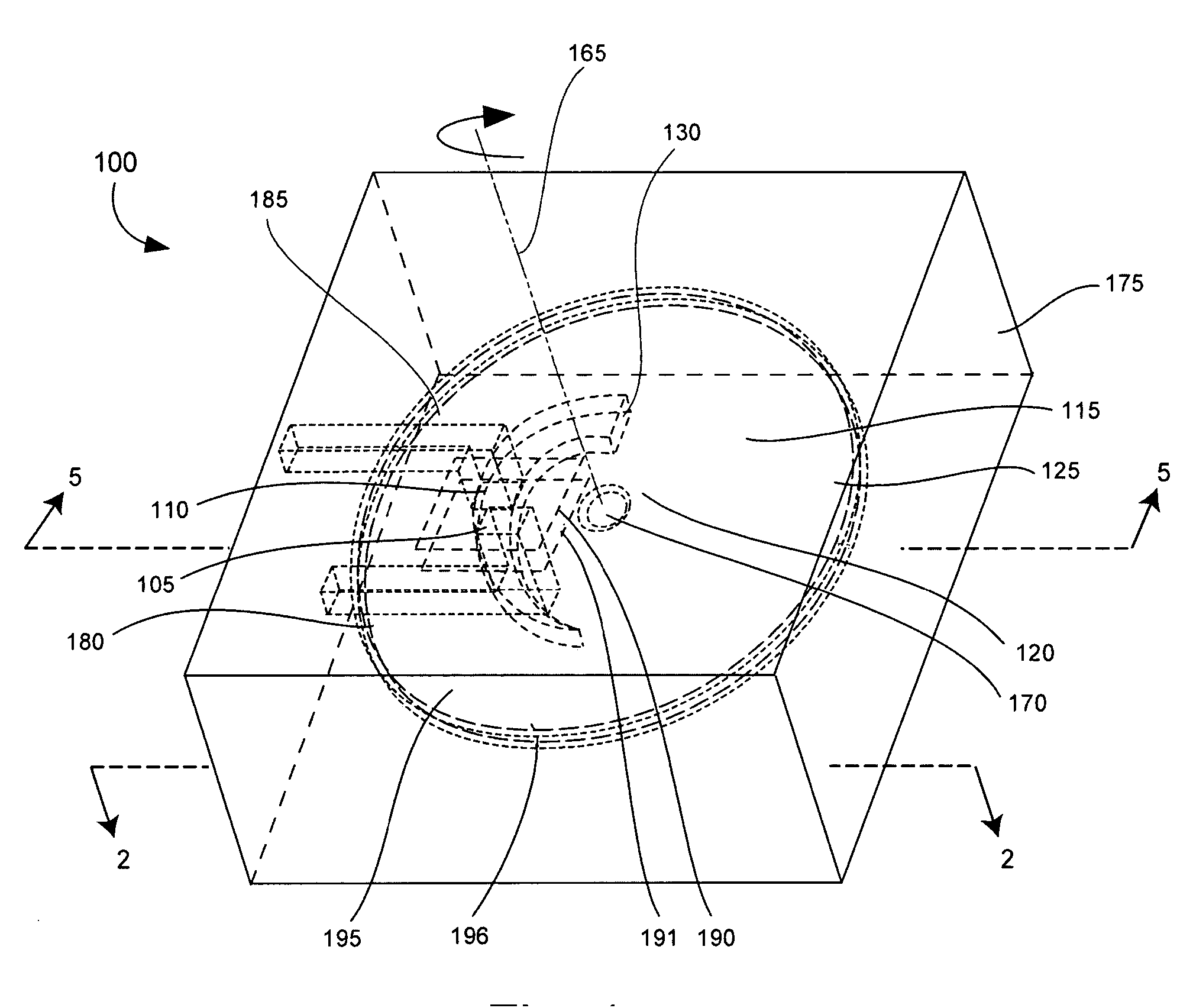
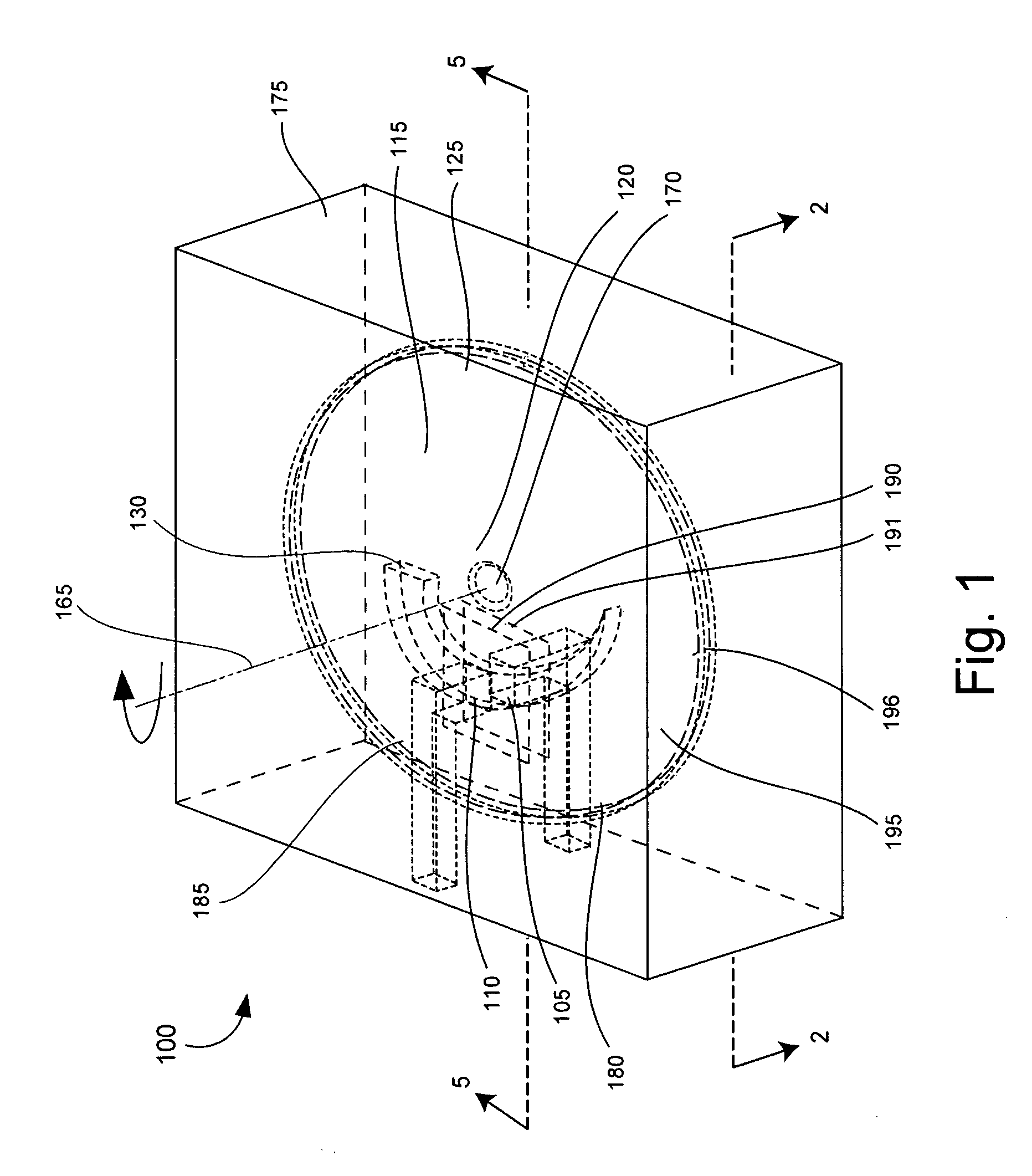
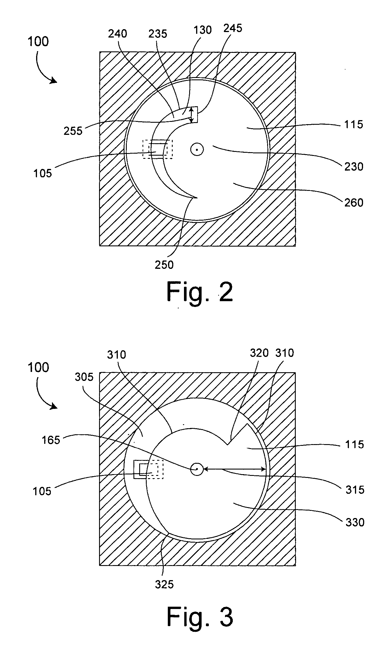
[0022] The present invention relates to a microfluidic control valve (control valve). The control valve can be used in microfluidic systems to control a fluid flow rate, as well as to turn on and turn off fluid flow. Importantly, the control valve can be embedded in a substrate containing a fluid flow channel through which the fluid flows. The control valve can include a microelectromechanical homopolar motor (homopolar motor) to impede fluid flow as required via rotation of a disk having at least one orifice through which the fluid can flow. Through the rotation of the disk, the alignment of the orifice with respect to a fluid flow port can be varied, and thus provide a variable fluidic impedance. Notably, the disk can be very small. For example, the disk can have a diameter that is smaller than 1 cm, or even smaller than 1 mm. Accordingly, the system profile of the microfluidic system is smaller in comparison to fluidic systems using discrete components. Additionally, there are a ...


PUM


Abstract

A method for controlling fluid flow. A fluid (560) can be communicated to a first fluid flow port (105) disposed adjacent to a first surface (196) of a rotatable disk (115) of a homopolar motor. The fluid can flow through at least one orifice (130) in the rotatable disk to a second fluid flow port (110). The rotation of the disk can be selectively controlled to vary a fluid flow rate. Further, the disk can be rotated to align a selected one of the orifices with at least one of the first and second fluid flow ports. In another arrangement, the shape of the orifice can have a radial width that increases in a circumferential direction.

Description

BACKGROUND OF THE INVENTION [0001] 1. Statement of the Technical Field [0002] The inventive arrangements relate generally to the field of micro devices, and more particularly to microfluidic control systems. [0003] 2. Description of the Related Art [0004] Miniaturization of various devices which incorporate fluidic systems has spurred a need for fluidic systems having very small components. These systems are commonly known as microfluidic systems. Microfluidic systems have the potential to play an increasingly important role in many developing technology areas. For example, there has been an increasing interest in recent years in the use of liquid fuels in microengines and in the use of fluid dielectrics in electronics systems. [0005] Another technological field where micro-fluidic systems are likely to play an increasingly important role is fuel cells. Fuel cells generate electricity and heat by electrochemically combining a fuel and an oxidant, via an ion-conducting electrolyte. S...

Claims


Application Information

Patent Timeline
Patent Type & Authority Applications(United States)
IPC IPC(8): F16K1/36
CPCF16K11/074F16K27/045F16K99/0001F16K99/0013F16K99/0034F16K99/0046F16K31/042F16K2099/008F16K2099/0082H01M8/04194Y02E60/50F16K27/048F16K2099/0073
Inventor KOENEMAN, PAUL B.
Owner HARRIS CORP
Why Eureka
Try Eureka