Homopolar motor phase

A unipolar motor, yoke technology, applied in unipolar motors, electrical components, electromechanical devices, etc.

Inactive Publication Date: 2013-02-27
SINTERTECH OF TOUR MANHATTAN
View PDF7 Cites 0 Cited by
  • Summary
  • Abstract
  • Description
  • Claims
  • Application Information

AI Technical Summary

Problems solved by technology

Depending on the application, these angular differences can be different, but from known prior art especi

Method used


Image

  • Homopolar motor phase
  • Homopolar motor phase
  • Homopolar motor phase

Examples


Embodiment Construction

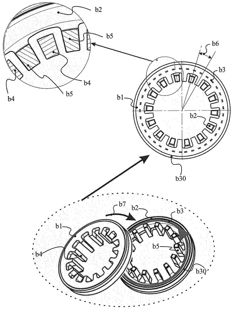
[0046] exist Image 6 The above invention shows a specific embodiment of a tooth formed by its tooth foot ( a5 ) and its tooth leg ( a3 ), which redirects the magnetic flux between two consecutive teeth ( a3 ) in the connecting surface, so that it takes a magnetic path other than the radial direction. This results in a corresponding increase in the copper cross section available for the winding ( b3 ).

[0047] exist Image 6 In the implementation, with the Figure 5 In the same manner as above, the magnetic flux Fd (a2) returns through the foot (a5) of each tooth. However, since the space (a6) existing between two consecutive tooth legs (a3) ​​of the tooth is filled with magnetic material, instead of Figure 5 The vacuum that exists on the surface, before reaching the opposite tooth (a5a) through the winding magnetic circuit, the magnetic flux Fd (a2) is divided into two magnetic fluxes Fc (a1), passing through the latter inter-tooth space (a6), subordinate to the phase (...


PUM


Abstract

The invention relates to a homopolar motor phase (d4) which consists of a wafer (a0), the leg (a3) of each tooth meeting the leg of the next tooth before touching the cylinder head (a4), said leg (a3) at least partially filling the space (a6) between the teeth. The inner diameter (a11) is reduced by the presence of a discontinuity in the area (a7) at the tip of the tooth (a5).

Description

technical field [0001] The invention relates to a rotating electrical machine with a unipolar structure. The rotating electrical machine with a unipolar structure includes a stator and a rotor rotating around the same rotating shaft as the stator. Shaped at least one electric coil carried by an annular yoke comprising at least two magnetic poles angularly diverging equidistantly from each other, the The yokes are joined together and consist of prongs folded parallel to said axis of rotation. Background technique [0002] The structure and operation of this type of motor, such as a rotary motor, are described in patent documents FR00 / 06298 and BR 18083 / FR (inventor: Bernot) described. [0003] figure 1 In the eight-pole version, the prior art is shown for this single-pole structure, which has a stator with three-phase claw poles and a rotor with surface magnets. Another version may include a rotor with embedded magnets. [0004] Another model may include a multi-phase s...

Claims


Application Information

Patent Timeline
IPC IPC(8): H02K1/14H02K37/14
CPCH02K37/14H02K31/00H02K1/145
Inventor F·贝尔诺A·贝尔诺
Owner SINTERTECH OF TOUR MANHATTAN
Why Eureka
Try Eureka