Eureka AIR delivers breakthrough ideas for toughest innovation challenges, trusted by R&D personnel around the world.

Superconducting devices, such as slip-rings and homopolar motors/generators

a technology of superconducting devices and slip-rings, which is applied in the direction of current collectors, dynamo-electric machines, electrical apparatus, etc., can solve the problems of chemical stability and compatibility, introduction of liquid containment problems, and the use of commonly used liquid metals also has problems. , to achieve the effect of reducing the number of insulating requirements and even safety hazards

Active Publication Date: 2017-08-31
MOOG INC
View PDF0 Cites 1 Cited by
  • Summary
  • Abstract
  • Description
  • Claims
  • Application Information

AI Technical Summary

Benefits of technology

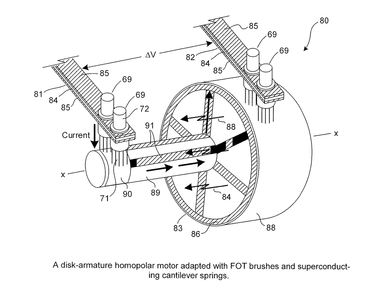
The present invention provides an improved device for providing electrical contact between a stator and a rotor. The device includes a stator with current-carrying brush-springs and fibrous brush assemblies mounted on the stator, each brush assembly having a bundle of fibers engaged with an associated rotor ring. The device is submerged in a cryogenic fluid to reduce electrical resistivity and increase the current-transferring capability. The invention also provides a method for providing a gold-on-gold electrical sliding contact between the rotor ring and the tips of metal fibers mounted in a brush assembly on the stator. The device and method may be used in various devices such as slip-rings, homopolar motors, and homopolar generators.

Problems solved by technology

Liquid metal current transfer systems have the advantage of essentially 100% area coverage of the slip-ring but they introduce problems of liquid containment, particularly for motors where inertial confinement techniques cannot be applied throughout the full operating speed range.
Commonly used liquid metals also have problems of chemical stability and compatibility, more stringent insulation requirements and even safety hazards.
The recent experimental results with solid and fiber brushes promise efficient collector operation with good brush life.In low voltage high current machines such as the homopolar (or unipolar) motor or generator, the current collector at conventional current densities is a major factor in machine size, weight and power loss.
For example, three potential effects of increased slip-ring coverage are as follows:(1) There is a concentration of power dissipation, which will result in excessive temperatures unless adequate cooling techniques are employed.(2) The reduced access time of the track surface to the surrounding atmosphere may influence the effectiveness of lubricating films in the form of adsorbed or chemisorbed surface layers and could result in higher friction and wear.(3) The increased concentration of wear debris, with reduced area for removal, could interfere with the intimacy of brush contact and possibly with the freedom of brush motion.In addition, when the brush current density is greatly increased, the sectional area of the shunt lead wire, between the brush and the stator conductor, must increase.
However, high-power homopolar motors with tens of megawatt ratings must carry enormous currents.
This poses design challenges in current collection, brush erosion and sparking.
135)] reviewed the development of superconducting homopolar motors, and concluded that brushes are the biggest challenge to the development of DC homopolar machines.
This article recites that solid carbon and metal-graphite brushes have been found inadequate due to their low current density capability and excessive wear.
Liquid metal brushes were reportedly also tried, but were deemed to be unsuitable due to material and life limitations.
Solid carbon or metal-graphite brushes were found inadequate due to their low current density capability and excessive wear.
Liquid metal brushes were also developed and applied to homopolar machines through the 1980s, but were not suitable for many applications due to material and life limitations.
A significant challenge is to control the brush losses in order to limit their maximum operating temperature.
For this reason[,] complex means for brush loading and liquid cooling of the rotor and stator are necessary.”
Early efforts in this regard were limited by the temperatures needed to cause various materials to transition to superconducting status.

Method used


Image

  • Superconducting devices, such as slip-rings and homopolar motors/generators
  • Superconducting devices, such as slip-rings and homopolar motors/generators
  • Superconducting devices, such as slip-rings and homopolar motors/generators

Examples


Embodiment Construction

[0084]At the outset, it should be clearly understood that like reference numerals are intended to identify the same structural elements, portions or surfaces consistently throughout the several drawing figures, as such elements, portions or surfaces may be further described or explained by the entire written specification, of which this detailed description is an integral part. Unless otherwise indicated, the drawings are intended to be read (e.g., cross-hatching, arrangement of parts, proportion, degree, etc.) together with the specification, and are to be considered a portion of the entire written description of this invention. As used in the following description, the terms “horizontal”, “vertical”, “left”, “right”, “up” and “down”, as well as adjectival and adverbial derivatives thereof (e.g., “horizontally”, “rightwardly”, “upwardly”, etc.), simply refer to the orientation of the illustrated structure as the particular drawing figure faces the reader. Similarly, the terms “inwa...


PUM


Abstract

A device (i.e., a slip-ring or a homopolar motor / generator) (40, 50, 80) is adapted to provide electrical contact between a stator and a rotor (41, 83), and includes: a current-carrying brush-spring (31, 84) mounted on the stator, and having two opposite surfaces; a fibrous brush assembly (35, 69) mounted on the conductor, the brush assembly having a bundle of fibers (36, 71) arranged such that the tips of the fibers will engage the rotor for transferring electrical current between the stator and rotor; a ribbon (33, 85) of superconducting material mounted on each opposite surface of the current-carrying brush-spring and communicating with the stator and the brush assembly; and another ribbon (29, 86) of superconducting material mounted on the rotor. The device is submerged in a cryogenic fluid at a temperature below the transition temperatures of the superconducting materials such that the electrical resistivity of the device will be reduced and the current-transfer capability of the device will be increased.

Description

TECHNICAL FIELD[0001]The present invention relates generally to electrical contacts for use with slip-rings, homopolar motors / generators, etc. that are used to transmit electrical power and / or signals between two members (e.g., a rotor and a stator), and, more particularly, to improved devices utilizing fiber-on-tips (“FOT”) brush technology and having ribbons of superconducting material(s) that have reduced electrical resistivity(ies) when cooled below their transition temperature(s) and that may transmit greatly-increased levels of electrical current between the members when so cooled.BACKGROUND ART[0002]Electrical contacts are used to transfer electrical power and / or signal(s) between a rotor and a stator. These devices are used in many different military and commercial applications, such as solar array drive mechanisms, aircraft and missile guidance platforms, wind energy systems, computed tomography (“CT scan”) systems, and the like. In some applications, slip-rings are used in...

Claims


Application Information

Patent Timeline
IPC IPC(8): H01R39/24H01R39/02H01R39/38H02K55/06H02K9/28
CPCH01R39/24H02K55/06H01R39/025H01R39/381H02K9/28H01R39/46H01R39/20
Inventor LEWIS, NORRIS E.WITHERSPOON, BARRY K.
Owner MOOG INC
Why Eureka
Eureka Blog
Learn More