Natural fiber span reflectometer providing a virtual phase signal sensing array capability

a technology of array capability and reflectometer, which is applied in the field of time domain reflectometers, can solve the problems of not showing how to obtain signals, fiber spans costing hundreds of thousands of dollars each, and the cost of manufacturing such perimeter monitoring spans employing reflective bragg grating sensors, etc., and achieves the effect of low cos

Active Publication Date: 2006-02-09
THE UNITED STATES OF AMERICA AS REPRESENTED BY THE SECRETARY OF THE NAVY
View PDF3 Cites 68 Cited by
  • Summary
  • Abstract
  • Description
  • Claims
  • Application Information

AI Technical Summary

Benefits of technology

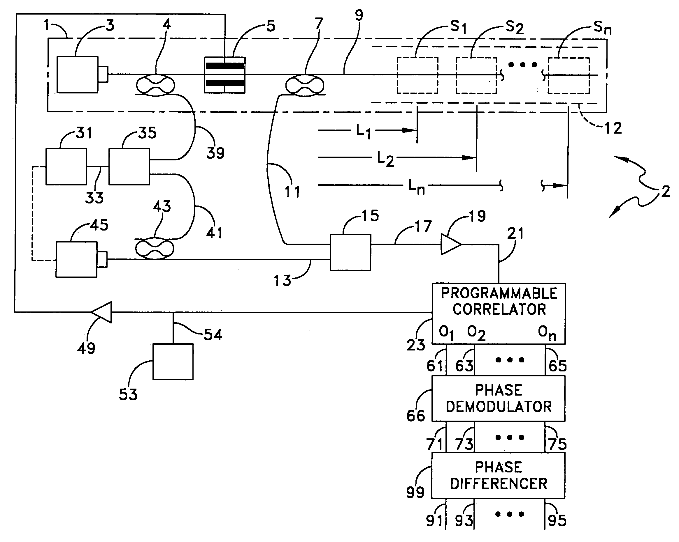
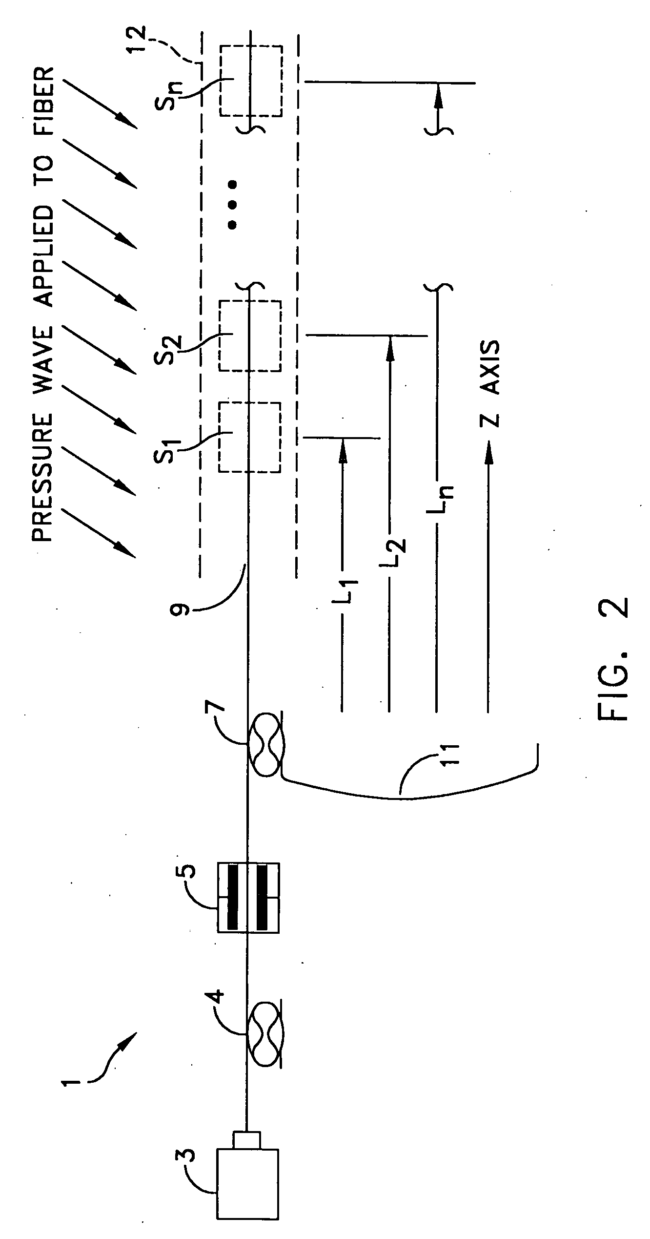
The invention provides an instrument called a time-domain reflectometer that can measure sound waves hitting a long stretch of fibre. This is done by making use of the natural properties of cheap commercial fibre optic cables, which have many tiny sensors along their length. These sensors provide data about the sound waves, allowing researchers to better analyze them.

Problems solved by technology

The technical problem addressed in this patent is finding ways to develop a more affordable way to make towed acoustic arrays or fiberspans that could be used for perimeter intrusion detection without requiring expensive Bragg reflected acoustic sensors.

Method used


Image

  • Natural fiber span reflectometer providing a virtual phase signal sensing array capability
  • Natural fiber span reflectometer providing a virtual phase signal sensing array capability
  • Natural fiber span reflectometer providing a virtual phase signal sensing array capability

Examples


Embodiment Construction

(1) Description of Underlying Theories

[0044] a. Heterodyne Optical Detection

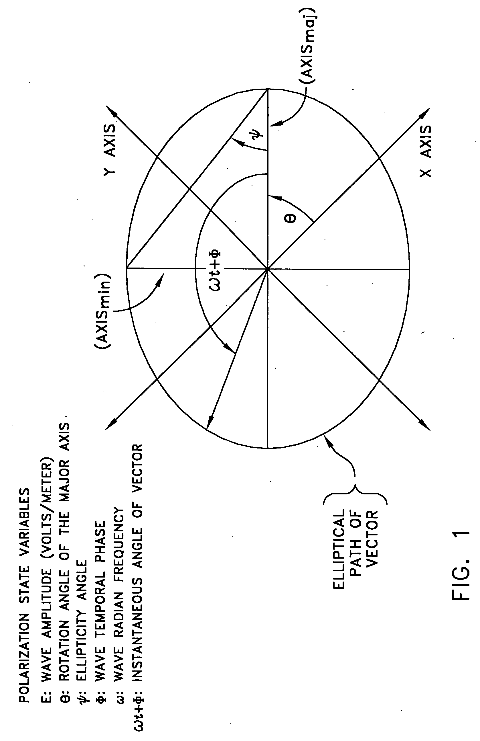
[0045] Optical receivers are built around photodetectors which detect optical power rather than instantaneous electric field. Typically the photodetector output current is proportional to the incident optical power. This relationship severely limits the dynamic range of an incoherent optical receiver because for every decibel of optical power lost in a receiver system two decibels of receiver output current is lost. The square law characteristics of photodetectors limits typical incoherent optical receivers (often called video detection receivers) to dynamic ranges of less than 80 dB and optical detection noise floors to greater than −80 dBm per Hertz bandwidth. As illustration, suppose an electric field ES(t) [volt / meter] immersed in a material of impedance η [Ohms] impinges upon a photodetector of responsivity R [ampere / watt] loaded by resistor R1 and amplified by amplification A, then the optical power...


PUM


Abstract

A CW lightwave modulated by a continuously reiterated psuedorandom code sequence is launched into an end of a span of ordinary optical fiber cable. Portions of the launched lightwave back propagate to the launch end from a continuum of locations along the span because of innate fiber properties including Rayleigh scattering. This is picked off the launch end and heterodyned producing a r.f. beat signal. The r.f. beat signal is processed by a plurality (which can be thousands) of correlator type pseudonoise code sequence demodulation and phase demodulator units, operated in different time delay relationships to the timing base of the reiterated modulation sequences. These units provide outputs representative of phase variations in respective unique spectral components in the r.f. beat signal caused by acoustic, or other forms of, signals incident to virtual sensors at fiber positions corresponding to the various time delay relationships.

Description


Claims


Application Information

Patent Timeline
Owner THE UNITED STATES OF AMERICA AS REPRESENTED BY THE SECRETARY OF THE NAVY
Why Eureka
Try Eureka