Magnetic head with high reliability of the data protection, magnetic disk apparatus including the magnetic head and the method of recording information on the magnetic disk apparatus without miserasing the previously recorded data

a technology of magnetic disk and data protection, which is applied in the field of magnetic disk apparatuses and magnetic heads, can solve the problems of further acceleration of thermal decay of recorded information, and achieve the effect of suppressing the acceleration of thermal decay and suppressing the thermal decay at the time of recording on the magnetic disk apparatus

Inactive Publication Date: 2006-02-09
HITACHI GLOBAL STORAGE TECH JAPAN LTD
View PDF5 Cites 2 Cited by
  • Summary
  • Abstract
  • Description
  • Claims
  • Application Information

AI Technical Summary

Benefits of technology

[0011] Furthermore, the present invention proposes an information recording system such that thermal decay is not easily accelerated.
[0034] Next, an information recording system in which thermal decay is not easily accelerated will be referred to. The method can suppress the acceleration of thermal decay attendant on appending of information onto a magnetic disk apparatus. Therefore, by using the method with the magnetic disk apparatus according to the present invention, the thermal decay at the time of recording on the magnetic disk apparatus can be suppressed, and the thermal decay on the magnetic disk apparatus attendant on repetition of recording can be effectively suppressed.

Problems solved by technology

Over-writing the same track repeatedly results in further acceleration of the thermal decay of the recorded information.

Method used


Image

  • Magnetic head with high reliability of the data protection, magnetic disk apparatus including the magnetic head and the method of recording information on the magnetic disk apparatus without miserasing the previously recorded data
  • Magnetic head with high reliability of the data protection, magnetic disk apparatus including the magnetic head and the method of recording information on the magnetic disk apparatus without miserasing the previously recorded data
  • Magnetic head with high reliability of the data protection, magnetic disk apparatus including the magnetic head and the method of recording information on the magnetic disk apparatus without miserasing the previously recorded data

Examples


first embodiment

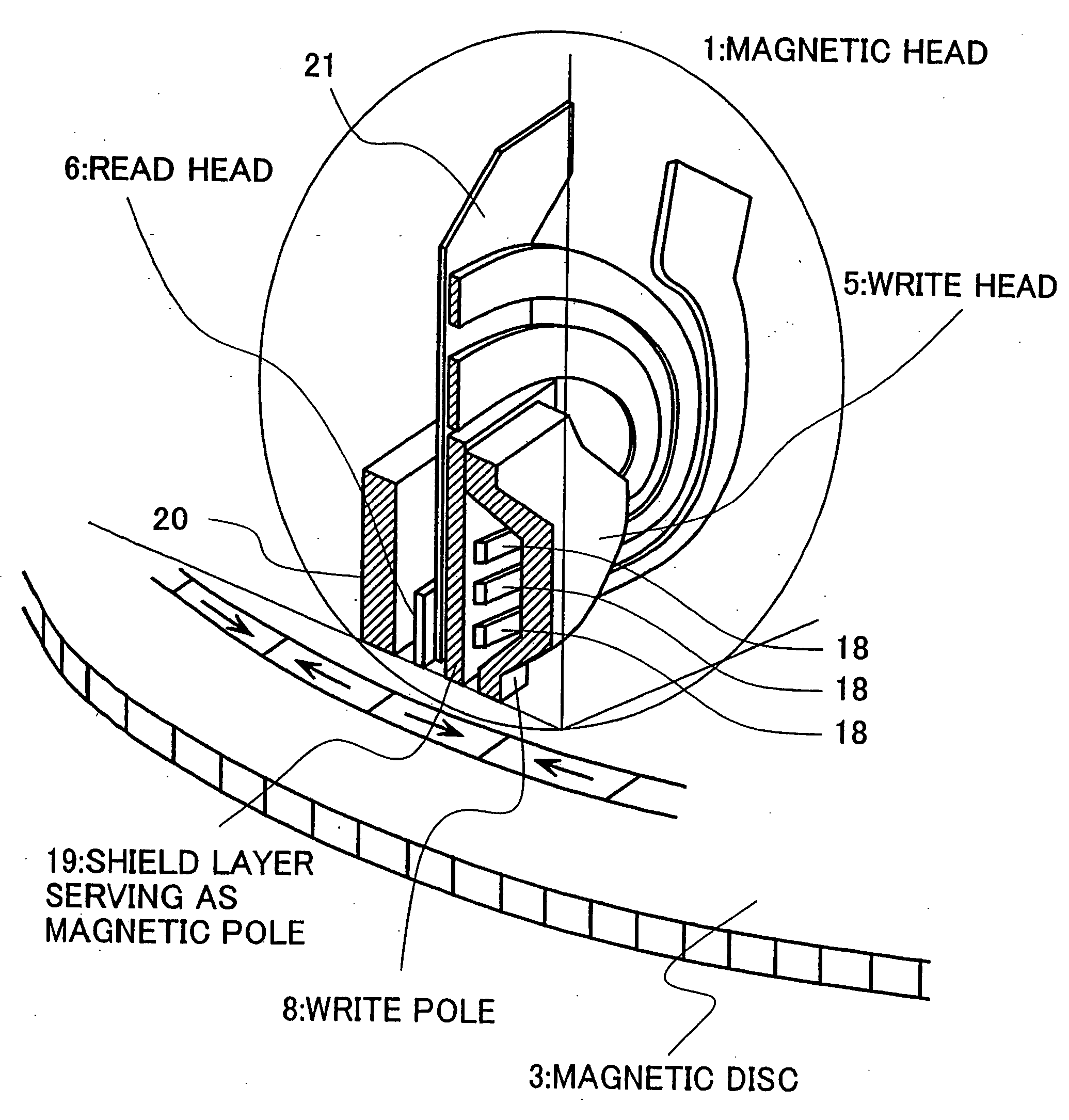
[0075]FIG. 7 shows the positioning relationship between a magnetic head and recording tracks according to the invention. The figure shows the positional relationship, as viewed from above, of a data track 10 and adjacent tracks 11, 12 in the case where the skew angle is S. The track pitch is denoted by numeral 13. As the magnetic head, only a first (lower) pole 15 and a second (upper) pole 9 are illustrated. The areas of symbols 10′, 11′ and 12′ in the figure are the areas of inversion of magnetization corresponding to recording tracks in the recording medium layer. This applies also in the similar figures.

[0076] In the present example, the projected length 14 of the upper pole 9 in the radial direction of disk is set to be not more than the track pitch. For this purpose, as shown in FIG. 7, a corner of the upper pole 9 is cut away so that the magnetic pole of the recording head does not overlap on the adjacent track portion.

[0077] More concrete description will be given below. The...

third embodiment

[0111] FIGS. 18(A) and 18(B) show another method of producing the magnetic head for use in the invention. FIG. 18(A) is a plan view of a magnetic pole formed by a prior-art method. The box-shaped area shown in FIG. 18(A) is trimmed by FIB from the head floating side, to produce the shape shown in FIG. 18(B).

[0112] FIGS. 19(A) and 19(B) show a further method of producing the magnetic head for use in the third embodiment of the invention. FIG. 19 (A) is a plan view of a magnetic pole formed by a prior-art method. As shown in FIG. 19 (A), Ar sputtering or ion milling is carried out in a skew direction to produce the shape shown in FIG. 19 (B). The sputtering or ion milling is preferably carried out in a skew direction of less than 90 degrees with respect to the track width direction.

[0113] In this method, the lower pole may be a little machined away, depending on the sputtering or milling conditions. In this method, therefore, it is preferable to control, for example, power condition ...


PUM

PropertyMeasurementUnit
skew angleaaaaaaaaaa
thicknessaaaaaaaaaa
skew angleaaaaaaaaaa

Abstract

There are provided a magnetic head and a magnetic disk apparatus wherein an upper magnetic pole is so shaped that, at a position where skew angle is maximum, the maximum of its projected length in the radial direction of a magnetic disk is not more than the track pitch of the magnetic disk, whereby acceleration of thermal relaxation of information recorded on adjacent tracks is obviated even in an area where the skew angle is large.

Description

[0001] This is a continuation of application Ser. No. 10 / 407,208, filed Apr. 7, 2003, which is a divisional of application Ser. No. 09 / 805,806 filed Mar. 13, 2001, the content of which is incorporated herein by reference in its entirety.BACKGROUND OF THE INVENTION [0002] 1. Field of the Invention [0003] The present invention relates to magnetic recording apparatuses, particularly magnetic disk apparatuses and magnetic heads. [0004] 2. Description of the Related Prior Art [0005] Magnetic disk apparatuses are classified into a longitudinal magnetic recording system and a perpendicular magnetic recording system, according to the direction of magnetization of a magnetic film. The perpendicular magnetic recording system can easily realize higher recording density than the longitudinal magnetic recording system, and are expected to be put to practical use in the future. An example of such magnetic heads is seen, for example, in the Journal of Magnetic Society of Japan, Vol. 19, Supplement...

Claims


Application Information

Patent Timeline
Patent Type & Authority Applications(United States)
IPC IPC(8): G11B19/04G11B5/147G11B5/012G11B5/02G11B5/187G11B5/31G11B5/48
CPCG11B5/012G11B5/02G11B5/4886G11B5/3116G11B5/313G11B5/1278
Inventor TOMIYAMA, FUTOSHIHAMAGUCHI, TAKEHIKOHARA, MIKIAKAGI, FUMIKONISHIDA, YASUTAKA
Owner HITACHI GLOBAL STORAGE TECH JAPAN LTD
Why Eureka
Try Eureka