Cleaning liquid dispensing in a mobile hard surface cleaner

a technology of cleaning liquid and hard surface cleaner, which is applied in the direction of carpet cleaners, floor surfacing/polishing machines, colloidal chemistry, etc., can solve the problems of impracticality, increased weight and energy requirements of the device, and limited operation runtim

Inactive Publication Date: 2006-02-16
TENNANT COMPANY
View PDF98 Cites 17 Cited by
  • Summary
  • Abstract
  • Description
  • Claims
  • Application Information

AI Technical Summary

Problems solved by technology

One problem with prior art hard floor surface cleaners has been their limited operational runtime.
This is primarily due to their limited solution tank volume and the high cleaning solution flow rates.
Unfortunately, such an increase in cleaning solution capacity typically necessitates modifications to the frame and other components of the hard floor surface cleaner, which results in additional weight and higher energy requirements for the device.
For most applications, these modifications are impractical.
Unfortunately, the lack of control of the volume flow rate of the cleaning solution results in an excessive amount of cleaning solution being distributed to the floor, when, for example, the solution tank is full.
The high volume flow rate of the cleaning solution of prior art hard floor surface cleaners also results in extended downtime.
Additionally, where the cleaning process removes harmful or hazardous chemicals, the disposal of the soiled cleaning solution may require special handling and / or additional costs to ensure that it is disposed of properly.
As a result, the large volumes of cleaning solution that are used by prior art hard floor surface cleaners reduce the efficiency at which a cleaning job can be performed.
Consequently, prior art hard floor surface cleaners suffer from several deficiencies that lead to inefficient floor cleaning operations.
Most of these deficiencies stem from the poor cleaning solution flow rate control and the high volume flow rate of the cleaning solution that is applied to the hard floor surface.

Method used


Image

  • Cleaning liquid dispensing in a mobile hard surface cleaner
  • Cleaning liquid dispensing in a mobile hard surface cleaner
  • Cleaning liquid dispensing in a mobile hard surface cleaner

Examples


Embodiment Construction

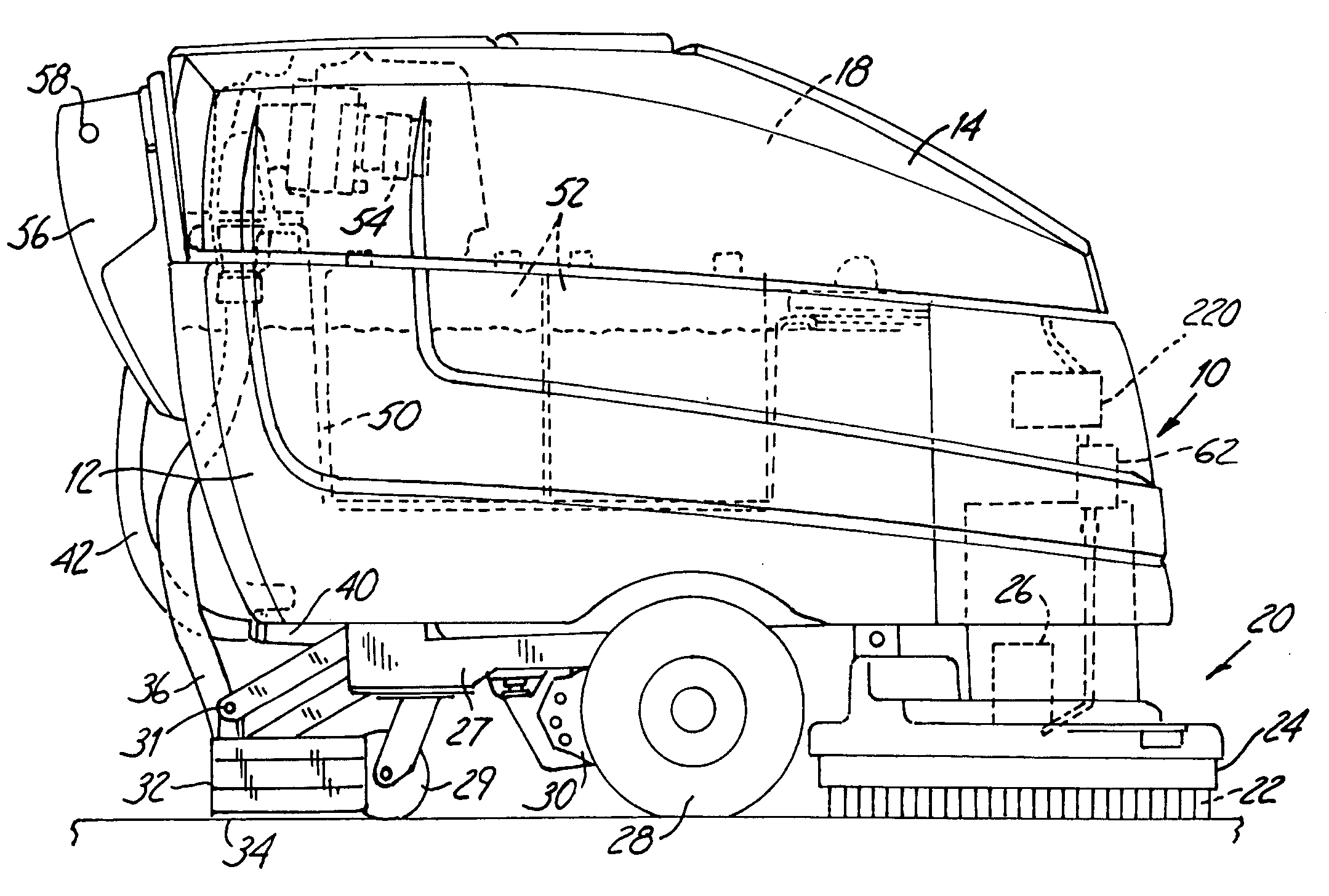
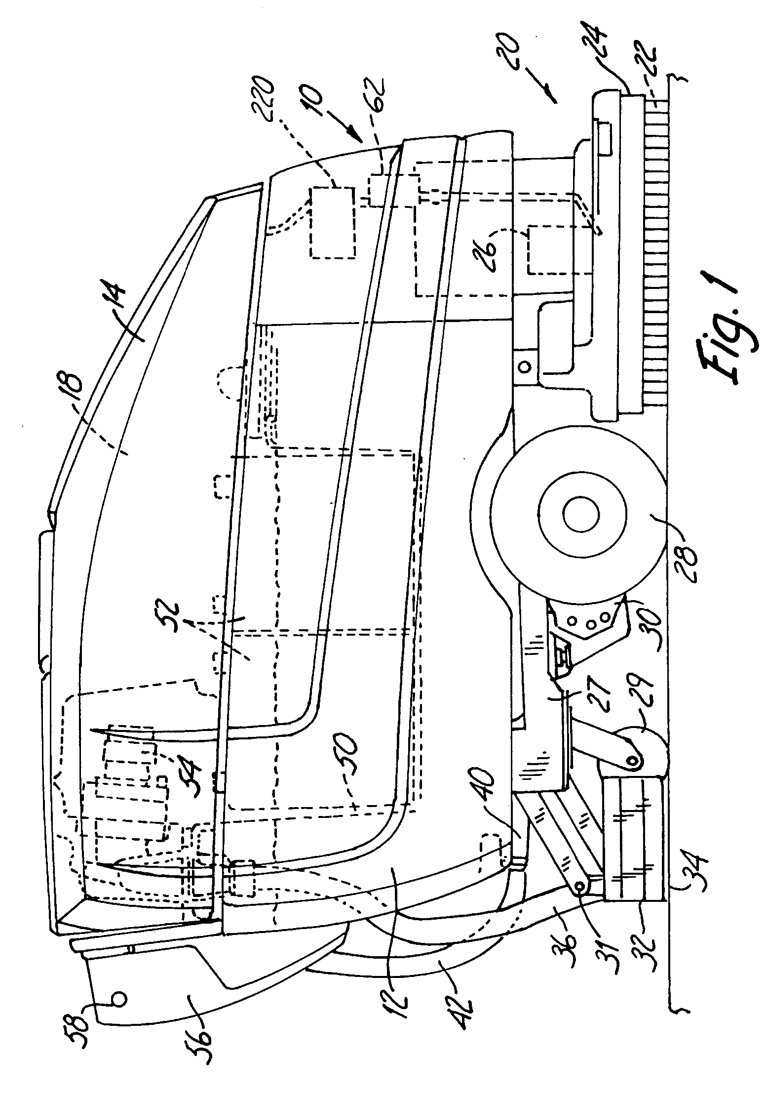
[0025]FIG. 1 illustrates a hard floor surface cleaner 10 in which embodiments of the present invention can be used. The illustrated cleaner 10 is a walk-behind cleaner used to clean hard floor surfaces, such as concrete, tile, vinyl, terrazzo, etc. Alternatively, cleaner 10 can be a ride-on or towed-behind cleaner performing a scrubbing operation as described herein. Cleaner 10 may include electrical motors powered through an on-board power source, such as batteries, or through an electrical cord. Alternatively, an internal combustion engine system could be used either alone, or in combination with, the electric motors. Cleaner 10 generally includes a recovery tank 12, and a lid 14. Lid 14 is attached along one side of the recovery tank 12 by hinges (not shown) so that lid 14 can be pivoted up to provide access to the interior of tank 12. Cleaner 10 also includes a tank 18 for containing cleaning liquid or a primary cleaning liquid component that is applied to the hard floor surface...


PUM

PropertyMeasurementUnit
sizeaaaaaaaaaa
pressureaaaaaaaaaa
diameteraaaaaaaaaa

Abstract

A hard surface cleaner includes a motorized scrub head, a fluid recovery device, a primary cleaning liquid component container, a cleaning agent container, a flow control device and a fluid flow path. The flow control device is configured to supply a flow of cleaning agent from the cleaning agent container at a flow rate of less than approximately cubic centimeters per minute to a flow of primary cleaning liquid component from the primary cleaning liquid component container. The fluid flow path is configured to receive a flow of cleaning liquid, which comprises the cleaning agent and the primary cleaning liquid component. A method of dispensing a chemical for use in a mobile hard surface cleaner includes driving a flow of cleaning agent from a cleaning agent container at a flow rate of less than approximately 10 cubic centimeters per minute, supplying a flow of primary cleaning liquid component from a cleaning liquid component container supported by the hard floor surface cleaner, combining the flow of cleaning agent and the flow of primary cleaning liquid component to form a flow of cleaning liquid, and dispensing the flow of cleaning liquid to either a motorized scrub head or a surface under the hard floor surface cleaner.

Description

[0001] This is a continuation of application Ser. No. 10 / 751,838, filed Jan. 5, 2004 and entitled “CHEMICAL DISPENSING METHOD FOR A HARD SURFACE CLEANER”, which is a continuation of application Ser. No. 10 / 152,537, filed May 21, 2002, entitled “CHEMICAL DISPENSER FOR A HARD FLOOR SURFACE CLEANER” and issued as U.S. Pat. No. 6,671,925, which is a continuation-in-part of U.S. application Ser. No. 10 / 026,411, filed Dec. 21, 2001, entitled “APPARATUS AND METHOD OF USE FOR CLEANING A HARD FLOOR SURFACE UTILIZING AN AERATED CLEANING LIQUID” and issued as U.S. Pat. No. 6,585,827, which in turn claims priority to U.S. Provisional Application Ser. No. 60 / 308,773, filed Jul. 30, 2001 and entitled “APPARATUS AND METHOD OF USE FOR CLEANING A HARD FLOOR SURFACE UTILIZING AN AERATED CLEANING LIQUID”; and this is a continuation-in-part of application Ser. No. 10 / 653,347, filed Sep. 2, 2003 and entitled “FOAMED CLEANING LIQUID DISPENSING SYSTEM”, which in turn is a continuation-in-part of U.S. appl...

Claims


Application Information

Patent Timeline
Patent Type & Authority Applications(United States)
IPC IPC(8): B08B7/00A47L7/00A47L11/03A47L11/16A47L11/18A47L11/29A47L11/30A47L11/34B01F3/04B01J13/00B65D77/06
CPCA47L11/03A47L11/30A47L11/302A47L11/305A47L11/4011B01J13/0095A47L11/4038A47L11/4044A47L11/4083A47L11/4088B01F3/04992A47L11/4016B01F23/291
Inventor FIELD, BRUCE F.KRUEGER, JOSEPH K.POULIOT, JOSEPH L.
Owner TENNANT COMPANY
Why Eureka
Try Eureka