

Display device
a technology for display devices and display areas, applied in the direction of discharge tubes/lamp details, discharge tubes luminescnet screens, electric discharge lamps, etc., can solve the problem of not completely preventing the spread of moisture remaining in the display area, and achieve the effect of reducing the deterioration of organic el devices due to moisture in the display area and preventing moisture in the peripheral area
- Summary
- Abstract
- Description
- Claims
- Application Information
AI Technical Summary
Benefits of technology
Problems solved by technology
Method used
Image

Examples
first embodiment
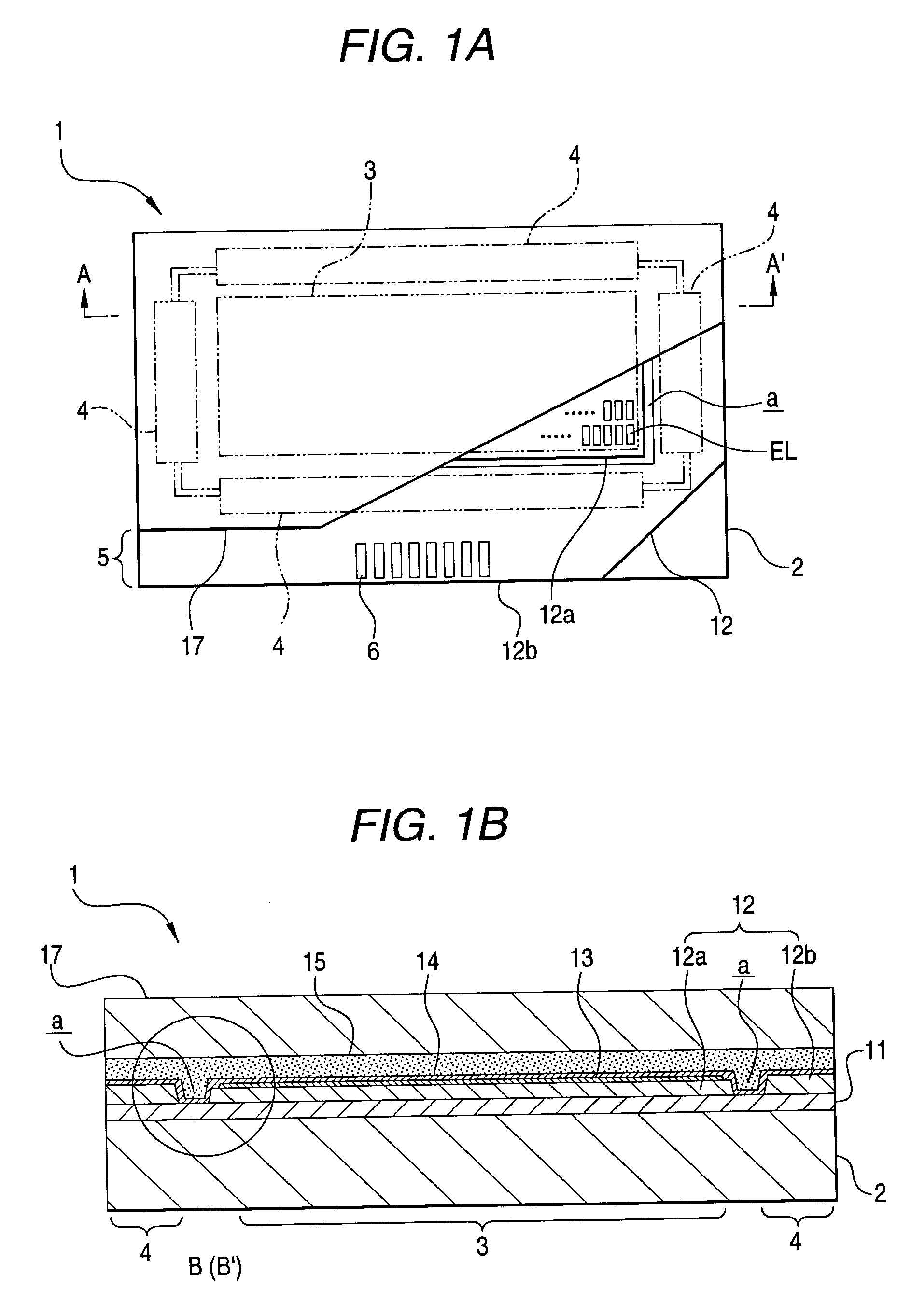
[0022]FIG. 1A is a plan view showing a construction of a display device of a first embodiment, and FIG. 1B is a schematic section view taken at Line A-A′ in FIG. 1A.
[0023] First of all, as shown in the plan view in FIG. 1A, a display device 1 is an organic EL display device including organic EL devices EL serving as light emitting elements. On a substrate (which is a supporting substrate here) 2, the display device 1 includes a display area 3, a peripheral area 4 surrounding the display area 3, and an implemented area 5. The substrate 2 is made of a transparent material such as glass. The display area 3 has a plurality of organic EL devices EL. An IC chip and / or a circuit substrate are implemented on the implemented area 5.
[0024] In the display area 3, each of pixels on the supporting substrate 2 has an organic EL device EL. When the display device 1 is an active-matrix display device, each pixel has an organic EL device and a pixel circuit (not shown) for driving the organic EL d...
second embodiment
[0046]FIGS. 3A and 3B are main part enlarged section views showing features in a display device according to a second embodiment. FIG. 3A shows an enlarged section view corresponding to Part B in the schematic section view in FIG. 1B, and FIG. 3B shows an enlarged section view corresponding to Part B′ in the schematic section view in FIG. 1B. A display device 1a according to the second embodiment shown in FIGS. 3A and 3B is different from the display device according to the first embodiment in that an inorganic layer 41 is provided at the bottom of the separating groove a for alleviating the degree of the level change due to the separating groove a. The other construction of the second embodiment is the same.
[0047] The inorganic layer 41 has a width W1, which is wider enough than the width W of the opening at the bottom of the separating groove a. The bottom of the separating groove a is configured to securely position on the inorganic layer 41 only so that the degree of the level ...
third embodiment
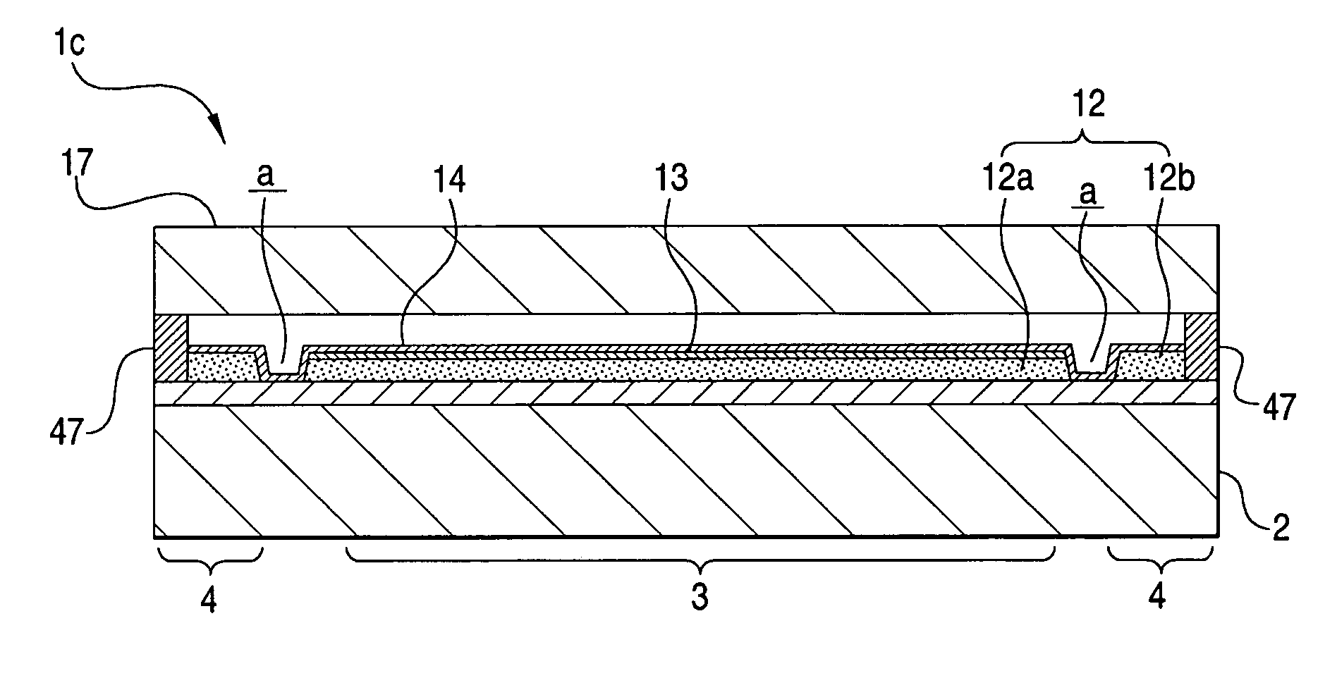
[0054]FIG. 4A is a plan view showing a construction of a display device according to a third embodiment, and FIG. 4B is a schematic section view taken at Line A-A′ in FIG. 4A. A display device lb shown in FIGS. 4A and 4B is different from the display devices of the embodiments above in that a sealed area 45 resulting from the removal of the organic insulating film 12 is provided in the outermost circumference of the part having the opposite substrate 17 over the supporting substrate 2, and the other construction is the same.
[0055] In other words, in the display device 1b, the separating groove a resulting from the removal of the organic insulating film 12 is provided between the display area 3 and the peripheral area 4 so that the display area 3 is surrounded. The sealed area 45 resulting from the removal of the organic insulating film 12 is provided surrounding the separating groove a and the perimeter of the peripheral area 4. The sealed area 45 is the outermost periphery of the ...
PUM
 Abstract
Description
Claims
Application Information