
Automatic channel selection method and apparatus in unstable digital channel environments

a digital channel and automatic channel technology, applied in the field of television signals, can solve the problems of signal dropping below a threshold level, signal cannot be displayed or poorly displayed, signal reception of digital signals,

Active Publication Date: 2006-02-16
SATURN LICENSING LLC
View PDF18 Cites 25 Cited by
  • Summary
  • Abstract
  • Description
  • Claims
  • Application Information

AI Technical Summary

Benefits of technology

[0009] A further embodiment may be characterized as an apparatus comprising a tuner for demodulating a first television signal; and a controller electronically coupled to the tuner, the controller configured to compare a value of a first variable to a threshold level, the value of the first variable related to a quality of the first television signal; wherein the controller switches from outputting for display the first television signal to outputting for display a second television signal that corresponds to the first television signal in response to comparing the value of the first variable to the threshold level.
[0010] Yet another embodiment may be characterized as an apparatus comprising a tuner module configured

Problems solved by technology

However, there are several disadvantages in the reception of digital signals.
For example, the transmission signal strength and signal stability can cause the digital signal to drop below a threshold level such that the signal can not be displayed or is poorly displayed.
Additionally, physical objects in the line of sight (e.g., aircraft), weather and unstable cable infrastructure also affect the signal level as well as their robustness (i.e., steady state signal level).
This can be a time consuming and inconvenient process during which time a person watching the television may miss an important part of the programming.

Method used


Image

  • Automatic channel selection method and apparatus in unstable digital channel environments
  • Automatic channel selection method and apparatus in unstable digital channel environments
  • Automatic channel selection method and apparatus in unstable digital channel environments

Examples


Embodiment Construction

[0017] The following description is not to be taken in a limiting sense, but is made merely for the purpose of describing the general principles of the invention. The scope of the invention should be determined with reference to the claims.

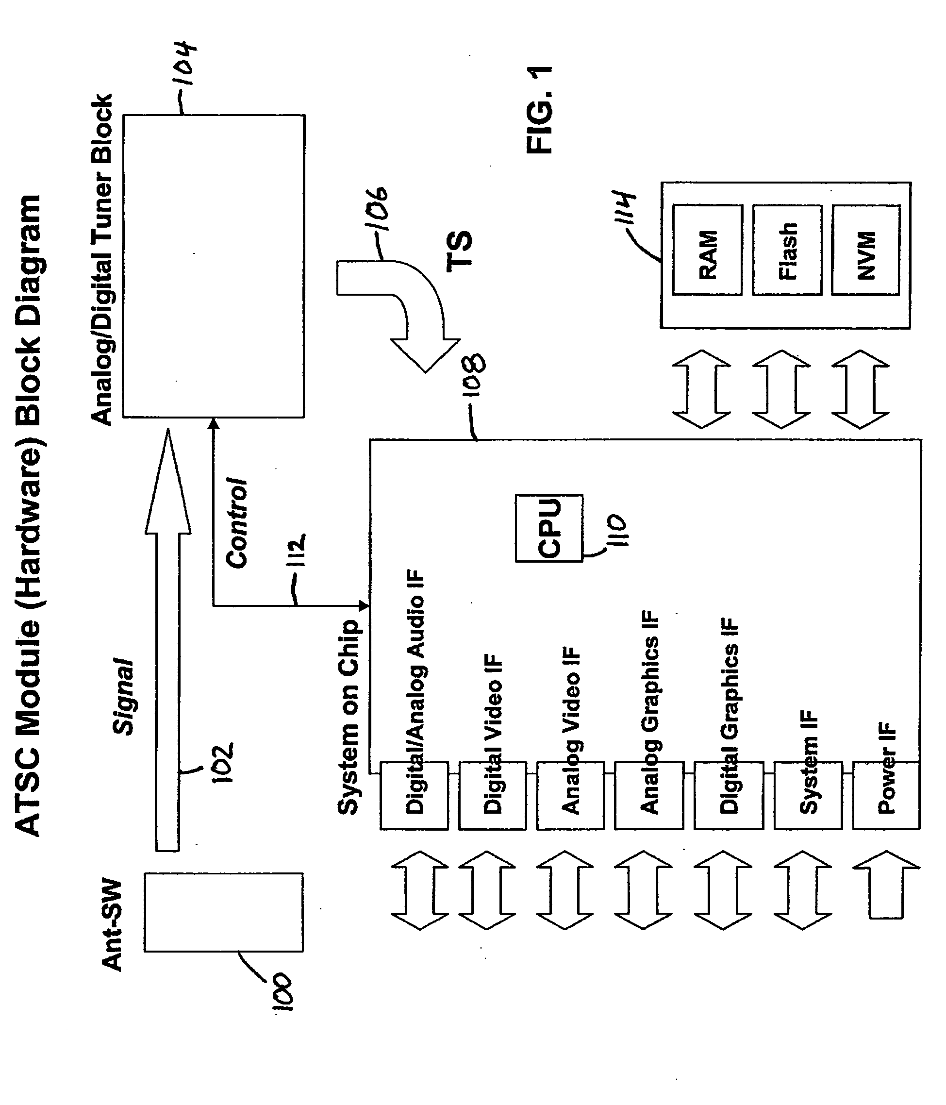
[0018] Referring to FIG. 1 a block diagram is shown illustrating a hardware configuration of a television in accordance with one embodiment. Shown is a antenna switch 100, an input signal 102, a tuner 104, a transport stream 106, a system on chip 108, a processor 110, a control line 112, and memory devices 114.

[0019] The antenna switch 100 is electrically coupled to the tuner 104 such that television signals can be sent to the tuner 104. The tuner 104 is electrically coupled to the system on chip 104 through both the transport stream 106 and the control line 112. The processor 110 is part of the system on chip 108. The system on chip 108 is also electrically coupled to the memory devices 114.

[0020] In operation, a television signal (e.g., cable...


PUM


Abstract

An apparatus comprising a tuner module configured to demodulate a first television signal and a second television signal that corresponds to the first television signal; and a controller electronically coupled to the tuner module, the controller configured to compare a value of a first variable to a threshold level, the value of the first variable related to a quality of the first television signal; wherein the controller switches from outputting for display the first television signal to outputting for display the second television signal that corresponds to the first television signal in response to comparing the value of the first variable to the threshold level.

Description

BACKGROUND OF THE INVENTION [0001] 1. Field of the Invention [0002] The present invention relates generally to television signals. Even more specifically, the present invention relates to a system and method for switching from a first television signal to a corresponding second television signal upon loss or interruption of the first television signal. [0003] 2. Discussion of the Related Art [0004] Reception and display of digital television signals delivers significant improvements in audio and picture quality as compared to the receipt and display of analog signals. However, there are several disadvantages in the reception of digital signals. For example, the transmission signal strength and signal stability can cause the digital signal to drop below a threshold level such that the signal can not be displayed or is poorly displayed. [0005] The quality of digital signals in terms of strength and stability depends on the proximity, direction, height and transmission power of the dig...

Claims


Application Information

Patent Timeline
IPC IPC(8): H04N17/02
CPCH04N5/4401H04N5/46H04N5/50H04N21/44209H04N21/4382H04N21/44016H04N21/42638H04N21/426
Inventor OZAKI, ARTHUR H.MCDERMOTT, MICHAEL DONALDSHINTANI, PETER
Owner SATURN LICENSING LLC
Learn More