Connector with conductors exposed to exterior air to facilitate heat removal

a technology of connecting conductors and exterior air, which is applied in the field of electrical devices, can solve the problems of insufficient heat dissipation of conductors, significant temperature rise of power connectors, and inability to optimize current technologies to dissipate away heat generated by conductors, etc., and achieves the effect of reducing the cost of solutions such as unnecessary

Inactive Publication Date: 2006-02-16
IBM CORP
View PDF6 Cites 12 Cited by
  • Summary
  • Abstract
  • Description
  • Claims
  • Application Information

AI Technical Summary

Problems solved by technology

As electrical current load through the power connector increases (as the power connector carries more current), a significant temperature rise in the power connector typically occurs.
Current connector technol...

Method used


Image

  • Connector with conductors exposed to exterior air to facilitate heat removal
  • Connector with conductors exposed to exterior air to facilitate heat removal
  • Connector with conductors exposed to exterior air to facilitate heat removal

Examples


Embodiment Construction

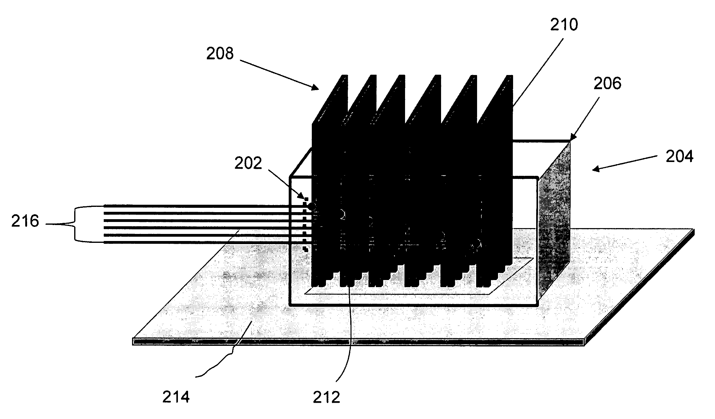
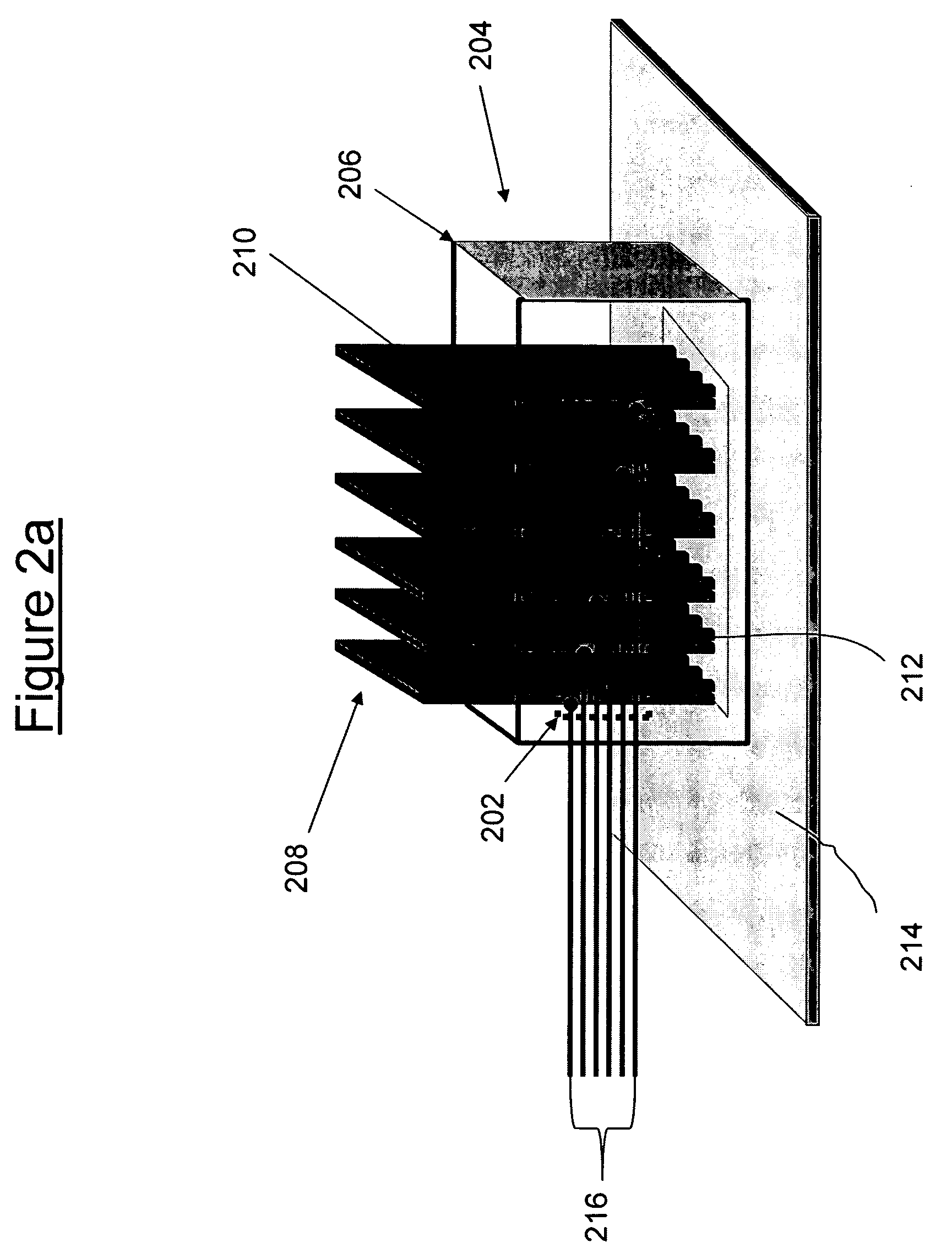
[0018] With reference now to FIGS. 2a-c, there is depicted a novel power connector 200, which is composed of a male power connector 202 (shown as being transparent) coupled to a female power connector 204. Female power connector 204 is composed of a conductor housing 206, which houses multiple conductors 208. Each conductor 208 has a power plate 210 that has an end from which multiple pins 212 extend. Pins 212 mate with holes (not shown) in a circuit board 214, which supplies pathways to other components (not shown), preferably those components that are mounted on circuit board 214. Each power plate 210 is connected to one of power supplying power lines 216, which feed into male power connector 202.

[0019] While shown as being transparent in FIG. 2a, in order to show the portions of conductors 208 that are internal to conductor housing 206, note that conductor housing 206 may either be solid (having plastic or a similar material between power plates 210), or else conductor housing 2...


PUM


Abstract

A power connector that uses ambient air to cool exposed power conductors through the use of either passive or forced air convection. The power conductors in the power connector are distributed for maximum contact with the cooling air. The power connector's housing is designed to cause maximum air flow across and/or against the power conductors.

Description

BACKGROUND OF THE INVENTION [0001] 1. Technical Field [0002] The present invention relates in general to the field of electronics, and in particular to power connectors. More particularly, the present invention relates to a method and system for conducting heat away from a power connector by exposing electrical conductors in the power connector to heat-removing ambient air. [0003] 2. Description of the Related Art [0004] In a modem computer, one source of heat inside the computer is a power circuit. The power circuit includes a power source, which supplies power to a power connector. The power connector is composed of a male power connector coupled with a female power connector. The female power connector has receptacles on one side for mating with the male power connector, and power supplying pins, on another side, that are soldered into holes in a printed circuit board. The printed circuit board provides pathways for power from the power supplying pins to multiple devices on the p...

Claims


Application Information

Patent Timeline
IPC IPC(8): H01R12/00
CPCH01R12/727
Inventor BOSCO, FRANK E.DOURIET, DANIELHUBER, ANDREAS
Owner IBM CORP
Why Eureka
Try Eureka