Drying cabinet shaker mechanism

a shaker mechanism and shaker technology, applied in the direction of drying machines, drying machines with materials at rest, light and heating apparatus, etc., can solve the problem of more expensive than desirable shaker mechanisms, and achieve the effect of facilitating wrinkle removal from clothes

Inactive Publication Date: 2006-02-23
MAYTAG
View PDF7 Cites 61 Cited by
  • Summary
  • Abstract
  • Description
  • Claims
  • Application Information

AI Technical Summary

Benefits of technology

[0009] The clothes drying cabinet of the present invention includes a drying chamber with a bar suspended in the chamber for receiving hangers with clothes. A motor is mounted in the chamber and connected to the bar. A drive weight is eccentrically mounted on the drive shaft of the motor so as to shake the bar when the mo...

Problems solved by technology

Such a shaker mechanism is more costly tha...

Method used


Image

  • Drying cabinet shaker mechanism
  • Drying cabinet shaker mechanism
  • Drying cabinet shaker mechanism

Examples


Embodiment Construction

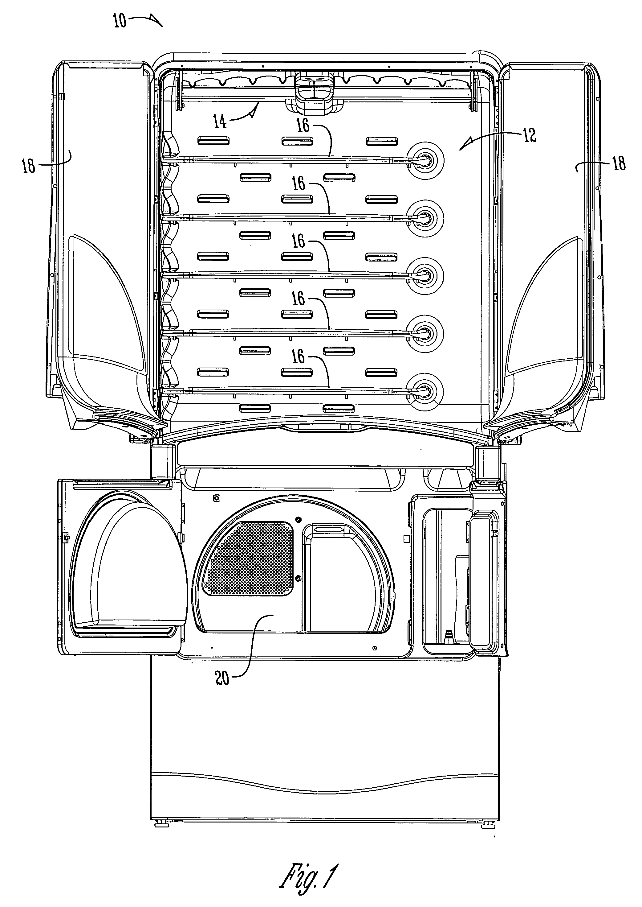
[0015] A cabinet dryer is generally designated by the reference numeral 10 in the drawings. The cabinet dryer 10 includes a drying chamber 12 with the shaker assembly 14 of the present invention. The chamber also includes removable shelves 16 which may be utilized when the shaker assembly is not needed. The cabinet dryer 10 includes a pair of doors 18 moveable between open and closed positions relative to the drying chamber 12. FIG. 1 shows the cabinet dryer 10 in combination with a tumble dryer 20, though it is understood that the tumble dryer is not a part of the present invention.

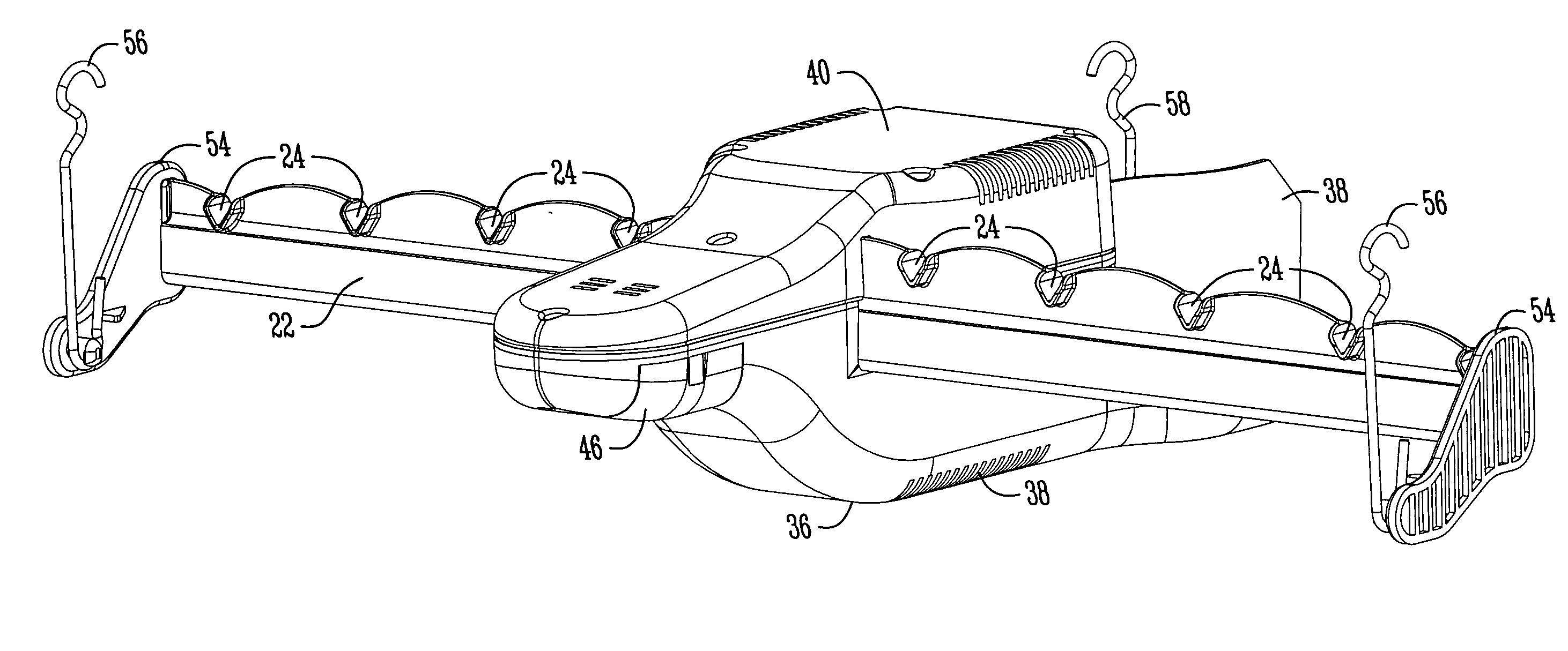
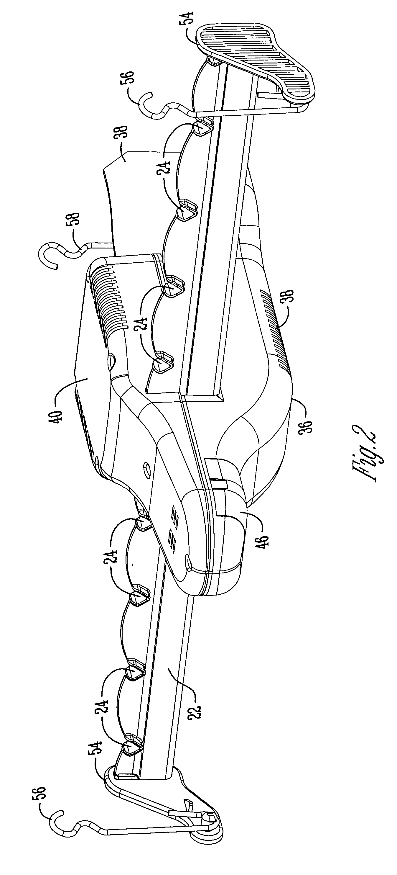
[0016] The details of the shaker assembly 14 are best seen in FIGS. 2 and 3. The shaker assembly 14 includes an elongated hanger bar 22 having a plurality of notches 24 adapted to receive conventional wire or plastic hangers (not shown).

[0017] The shaker assembly 14 also includes a drive motor 26 which is adjacent the bar 22. The motor 26 includes a drive shaft 30. A drive weight 32 is eccentrically mo...


PUM


Abstract

A clothes drying cabinet is provided with a shaker assembly including a bar suspended in the cabinet for supporting clothes hangers. A motor is mounted adjacent the bar and has a drive shaft. A drive weight is eccentrically mounted to the drive shaft of the motor so that upon actuation of the motor, the drive weight imparts a shaking motion to the bar so as to facilitate removal of wrinkles from the clothing on the hangers. A ballast weight may also be provided in the shaker assembly so as to evenly distribute the energy from the eccentric weight regardless of the weight of the clothes hanging on the bar.

Description

BACKGROUND OF THE INVENTION [0001] Clothes drying cabinets generally include a chamber or enclosure with a bar for supporting hangers with clothes. Some cabinets provide mechanisms for shaking the bar so as to facilitate wrinkle removal from the clothes while drying in the cabinet. For example, published U.S. Patent Application No. 2003 / 0223309 discloses a clothes hanger bar supported within a drying cabinet at four points, with a rotating disk to impart oscillating motion to the hanger bar via elastic cords extending between the disk and opposite side walls of the cabinet. Such a shaker mechanism is more costly than desirable, due in part to multiple components. [0002] Therefore, a primary objective of the present invention is the provision of an improved shaker assembly for a clothes drying cabinet. [0003] Another objective of the present invention is the provision of a shaker mechanism for a clothes drying cabinet which efficiently, effectively, and economically provides shaking ...

Claims


Application Information

Patent Timeline
IPC IPC(8): F26B19/00F26B9/00
CPCD06F73/02D06F58/10
Inventor JOHNSON, TROY A.SCHAFFRAN, DEAN L.
Owner MAYTAG
Why Eureka
Try Eureka