
Knee bolster mounting structure for a glove box

a glove box and mounting structure technology, applied in the direction of vehicular safety arrangments, pedestrian/occupant safety arrangements, vehicle components, etc., can solve the problem of non-uniform fusion between the fuse ribs and the glove box

Inactive Publication Date: 2006-02-23
HYUNDAI MOBIS CO LTD
View PDF7 Cites 31 Cited by
  • Summary
  • Abstract
  • Description
  • Claims
  • Application Information

AI Technical Summary

Benefits of technology

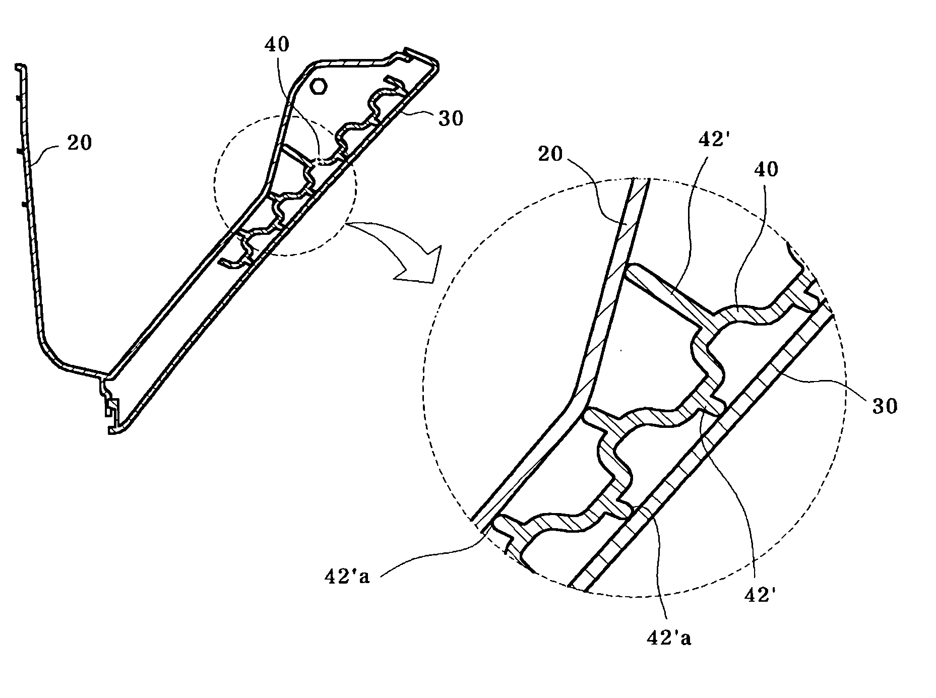
[0009] The present invention has been made to solve the above problems, and it is an object of the present invention to provide a knee bolster mounting structure for a glove box, designed to have a round portion formed on each end of a plurality of fuse ribs of the knee bolster so as to allow the fuse ribs to have a uniform contact area at the ends to a housing and a cover of the glove box, irrespective of a direction in which the fuse ribs contact the housing and the cover, so that the knee bolster is uniformly joined to the housing and the cover of the glove box, thereby preventing any whitening phenomenon.

Problems solved by technology

For example, for some fuse ribs 42, a whitening phenomenon occurs on an outer surface of the glove box due to excessive fusion of the fuse ribs 42, and for other fuse ribs 42, the ends of the fuse ribs 42 are minimally fused to the glove box, and provide insufficient bonding strength, resulting in non-uniform fusion between the fuse ribs and the glove box.

Method used


Image

  • Knee bolster mounting structure for a glove box
  • Knee bolster mounting structure for a glove box
  • Knee bolster mounting structure for a glove box

Examples


Embodiment Construction

[0016] Preferred embodiments will now be described in detail with reference to the accompanying drawings. Like components having similar functions to those of the conventional knee bolster mounting structure for the glove box will be denoted by like reference numerals of the conventional knee bolster mounting structure for the glove box.

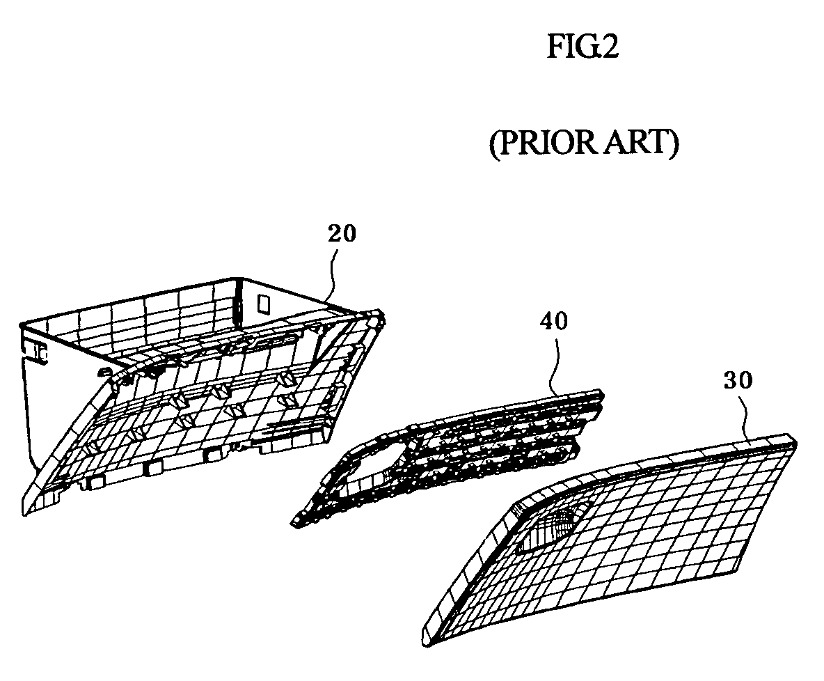
[0017] As shown in the drawings, a knee bolster integrating glove box in accordance with the present invention comprises a housing 20, which has a predetermined space defined therein and is hinged at a lower end thereof to an instrument panel, a cover 30, which is coupled to the front side of the housing 20 to form the outer appearance of the glove box and has a locking device equipped to one side of a front surface of the cover 30, and a knee bolster 40, which is interposed between the housing 20 and the cover 30 to absorb any impact, which can be applied to a passenger by the cover 30 in case of any collision.

[0018] Here, the housing 20 has a pre...


PUM

PropertyMeasurementUnit
Areaaaaaaaaaaa

Abstract

A knee bolster mounting structure for a glove box having a housing having a predetermined space defined therein, a cover coupled to a front side of the housing to form an outer appearance of the glove box, and a knee bolster interposed between the housing and the cover to absorb impact in case of collision includes a plurality of fuse ribs protruded from front and rear surfaces of the knee bolster and fused thereto by vibration fusion, respectively, and round portions formed on each end of the fuse ribs.

Description

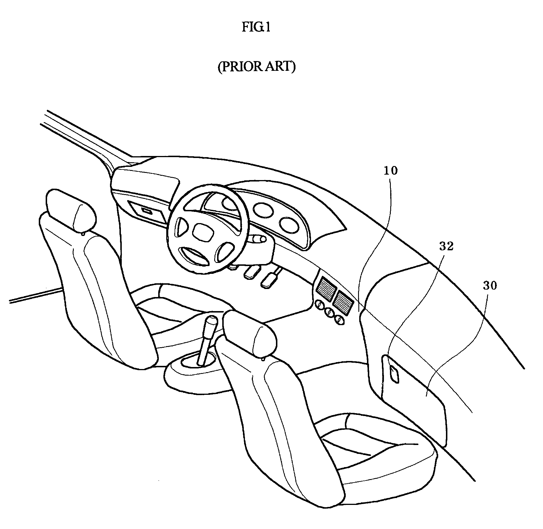
RELATED APPLICATIONS [0001] The present disclosure relates to subject matter contained in Korean Application No. 10-2004-0064751, filed on Aug. 17, 2004, which is herein expressly incorporated by reference its entirety. BACKGROUND OF THE INVENTION [0002] 1. Field of the Invention [0003] The present invention relates to a knee bolster integral to a glove box, and more particularly, to a knee bolster mounting structure for a glove box, which has an enhanced structure of fuse ribs in the knee bolster so as to enable the plurality of fuse ribs to contact the housing and a cover while maintaining a uniform contact area between the fuse ribs and the housing and between the fuse ribs and the cover, thereby allowing uniform assembly there between. [0004] 2. Description of the Related Art [0005] A glove box used for a vehicle is a space defined in a right lower end of an instrument panel 10, as shown in FIG. 1, to contain small articles and the like, and a knee bolster 40 is a reinforcing pa...

Claims


Application Information

Patent Timeline
IPC IPC(8): B60R21/045
CPCB60R21/045B60R2021/0414B60R2021/0051B60R7/06B29C66/545B60R21/055
Inventor CHO, JOUNG-HWAN
Owner HYUNDAI MOBIS CO LTD
Learn More