System for automatically gathering battery information for use during battery testing/charging

a battery information and automatic collection technology, applied in the field of storage batteries, can solve the problems of inaccurate battery test, improper battery charging, and bad battery determination

Inactive Publication Date: 2006-02-23
MIDTRONICS
View PDF99 Cites 127 Cited by
  • Summary
  • Abstract
  • Description
  • Claims
  • Application Information

AI Technical Summary

Problems solved by technology

If the voltage is below a certain threshold, the battery is determined to be bad.
Reliance on user entry of battery information may result

Method used


Image

  • System for automatically gathering battery information for use during battery testing/charging
  • System for automatically gathering battery information for use during battery testing/charging
  • System for automatically gathering battery information for use during battery testing/charging

Examples


Embodiment Construction

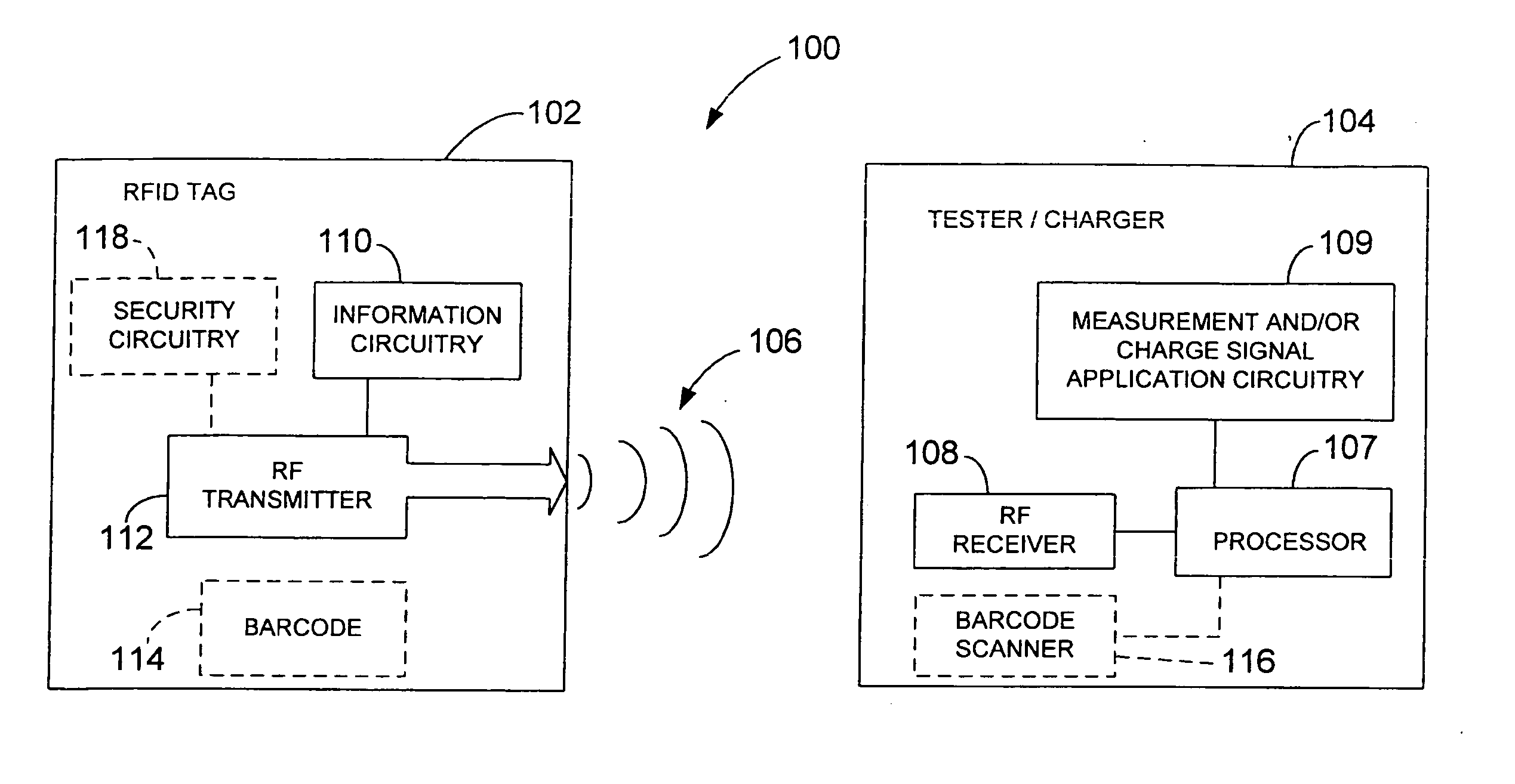
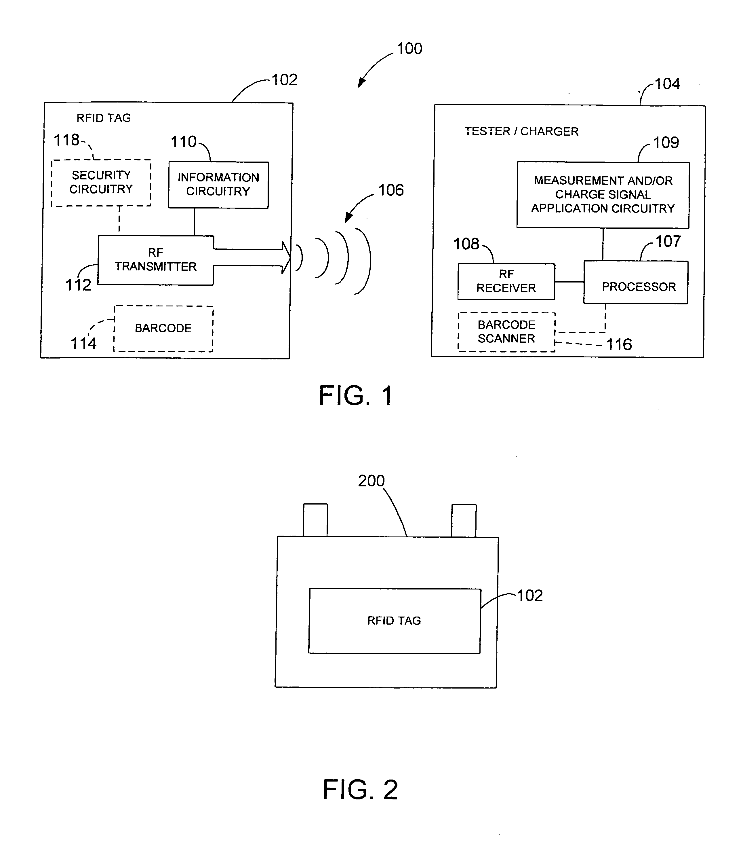
[0012]FIG. 1 is a simplified block diagram of a battery testing / charging system 100 in accordance with an embodiment of the present invention. System 100 includes a radio frequency identification (RFID) tag 102, which can be affixed to a battery (such as 200 (FIG. 2)). RFID tag 102 is configured to transmit stored battery information in the form of RF signals 106. System 100 also includes a battery tester / charger 104 having an embedded / integrated radio frequency (RF) receiver 108, which is configured to receive the transmitted battery information form RF tag 102 when battery tester / charger 104 is proximate RF tag 102. The battery information, which is automatically received by RF receiver 108, is utilized by processor 107 and measurement and / or charge signal application circuitry 109 to test / charge the battery (such as 200 (FIG. 2)). Thus, system 100 overcomes problems with prior art testers / chargers that, in general, require a tester / charger user to enter battery information with t...


PUM


Abstract

An apparatus and method for testing/charging a storage battery includes a radio frequency identification (RFID) tag that can be affixed to the storage battery, the RFID tag is configured to store and transmit information related to the battery. The apparatus also includes a battery tester/charger. The tester/charger includes a radio frequency (RF) receiver configured to receive the transmitted information related to the battery, and testing/charging circuitry configured to utilize the received information related to the battery to test/charge the storage battery.

Description

[0001] The present application is based on and claims the benefit of U.S. provisional patent application Ser. No. 60 / 603,078, filed Aug. 20, 2004, the content of which is hereby incorporated by reference in its entirety.BACKGROUND OF THE INVENTION [0002] The present invention relates to storage batteries. More specifically, the present invention relates to a system for automatically gathering battery information for use during battery testing / charging. [0003] Storage batteries, such as lead acid storage batteries, are used in a variety of applications such as automotive vehicles and stand by power sources. Typically, storage batteries consist of a plurality of individual storage cells which are electrically connected in series. Each cell can have a voltage potential of about 2.1 volts, for example. By connecting the cells in series, the voltages of individual cells are added in a cumulative manner. For example, in a typical automotive battery, six storage cells are used to provide a...

Claims


Application Information

Patent Timeline
IPC IPC(8): G01N27/416
CPCG01R31/3648H01M2/0267H02J2007/0098H01M10/488H02J7/0009H01M2/0275H02J7/00043H01M10/4257H02J7/00047Y02E60/10
Inventor PHILBROOK, JOHN S.
Owner MIDTRONICS
Why Eureka
Try Eureka